
1. Introduction
This blog describes how to deploy a quantum-resistant IPsec tunnel between two IPsec gateways as shown in figure 1 below.

Figure 1: IPsec tunnel between two Palo Alto VM-Series firewalls running in AWS
Future quantum computers will be able to break cryptographic algorithms such as Diffie-Hellman, Rivest Shamir Alderman (RSA), and Elliptic Curve Digital Signature Algorithm (ECDSA), which are currently used in IPsec.
There are several methods for fixing this problem by making IPsec tunnels quantum-resistant. One method is called Post Quantum Cryptography (PQC). Another method is called Quantum Key Distribution (QKD). We briefly describe each method, but in this blog we focus on PQC. Some time ago we already published another blog that focused on QKD. Also, in February 2025 we presented a 45-minute free online seminar on deploying quantum-safe IPsec which summarizes the information in both the PQC and the QKD blog.
Chapter 2 provides an introduction to IPsec. It describes what services IPsec provides, what applications IPsec is used for, and gives a brief overview of the IPsec protocols.
Chapter 3 describes what it means for IPsec to be quantum-vulnerable. It introduces the basic concepts of quantum computing, Shor’s algorithm, Grover’s algorithm, Post Quantum Cryptography (PQC), and Quantum Key Distribution (QKD).
Chapter 4 describes how the IPsec protocols have been extended to support PQC.
Chapter 5, finally, provides hands-on step-by-step instructions for configuring a quantum-resistant IPsec tunnel using PQC. If you are not interested in the theory and want to get straight to the hands-on configuration example, you may want to skip ahead to chapter 5.
We use Palo Alto VM-Series firewalls running in the Amazon Web Services (AWS) public cloud. Palo Alto is not the only vendor that supports quantum-resistant IPsec. As of January 2025, when this blog was written, Cisco, Juniper, and Fortinet all support some flavor of quantum-resistant IPsec. Some support the PQC flavor, some support the QKD flavor, and some support both.
The hands-on part of the tutorial consists of the following steps:
- Deploy two IPsec gateways instances in AWS.
- Configure private and public IP subnetworks in AWS to connect the two gateways.
- Configure the two firewalls to create a traditional IPsec tunnel between the two gateways.
- Add additional configuration to make the IPsec tunnel quantum-resistant using PQC.
- Verify that the IPsec tunnel works, by sending some traffic through it.
- Use show commands and the web interface to monitor the IPsec tunnel.
2. An introduction to IPsec
IPsec is not one single protocol; it is a very large and complex suite of protocols with numerous features. In this chapter we give a brief overview of the subset of IPsec that is relevant for quantum-resistance, focusing mainly on key exchange and authentication.
2.1 IPsec applications
IPsec enables the secure exchange of data over an untrusted network, such as the public Internet. More specifically, IPsec provides the following security functions:
- Confidentiality: encrypt packets to conceal their content.
- Authentication: verify that received packets were sent by the claimed sender.
- Integrity: verify that the contents of packets were not changed in transit.
- Replay prevention: protect against unauthorized retransmission of packets.
- Compression: reduce the size of packets using lossless compression.
- Network Address Translation (NAT) traversal: allow packets to pass through NAT.
- Traffic Flow Confidentiality (TFC): hide traffic patterns.
As the name suggests, IPsec is used to secure IP traffic (IPv4 or IPv6) at layer 3 of the OSI reference model. There are other security protocols to protect traffic at other layers, such as Media Access Control security (MACsec) for layer 2 and Transport Layer Security (TLS) for layer 4. We could write similar tutorials on how to deploy those protocols in a quantum-resistant manner.
IPsec is typically used to implement Virtual Private Networks (VPNs). The two most common types of VPNs are:
- Host-to-gateway VPNs (also known as remote-access VPNs) are used to connect remote workers to the corporate network over the public Internet (figure 2).
- Gateway-to-gateway VPNs are used to connect multiple corporate networks (for example branch office networks and headquarter networks) to each other over the public Internet (figure 3).
In this tutorial we focus on gateway-to-gateway VPNs, but the quantum-resistance features described here also apply to host-to-gateway VPNs.
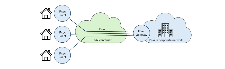
Figure 2: Host-to-gateway VPN using IPsec

Figure 3: Gateway-to-gateway VPN using IPsec
2.1 IPsec standards
IPsec was standardized by the IP Security Protocol (IPsec) and IPsec Maintenance and Extensions (IPsecME) working groups in the Internet Engineering Task Force (IETF). The protocols can be classified into three groups:
- Data-plane protocols that encapsulate user-data IP packets to provide security (encryption, integrity-protection, authentication, replay-protection, etc.) There are two encapsulations: IP Authentication Header (AH) [RFC4302] and IP Encapsulating Security Payload (ESP) [RFC4303]. We discuss the IPsec data-plane protocols in section 2.3.
- Control-plane protocols that authenticate communicating peers, create and manage security associations, negotiate the attributes of security associations (e.g. encryption keys), etc. There are many RFCs in this area; in this tutorial we focus on Internet Key Exchange Protocol Version 2 (IKEv2) [RFC5996]. We discuss the concept of security associations in section 2.4 and IKEv2 in section 2.5.
- Management-plane protocols that define information models for managing IPsec. We don’t cover management protocols in this tutorial.
The Security Architecture for the Internet Protocol [RFC4301] describes how these protocols fit together. The IP Security (IPsec) and Internet Key Exchange (IKE) Document Roadmap [RFC6071] provides a snapshot of all IPsec-related standards as of 2011. For an up-to-date complete list of IPsec related standards, see the document list web pages of the IPsec and IPsecME working groups.
The IPsecME working group has started standardizing extensions to IPsec for quantum-resistance. Some of the extensions have already been published as RFCs, some are still in the pre-standard Internet-Draft (I-D) stage.
The Post-Quantum Use in Protocols (pquip) IETF working group is working on quantum-resistance considerations that span multiple protocols (including IPsec but also other protocols).
IPsec has always made extensive use of crypto protocols that are standardized by the National Institute of Standards of Technology (NIST) in the United States of America.
NIST has recently (August 2024) standardized the first batch of quantum-resistant crypto protocols, including Module-Lattice-Based Key-Encapsulation Mechanism (ML-KEM) [FIPS203] to replace the quantum-vulnerable Diffie-Hellman protocol. We discuss Diffie-Hellman in section 2.5.3 and ML-KEM in section 4.3.
In this tutorial we only discuss PQC extensions to IPsec. We have already discussed QKD extensions to IPsec in a separate previous tutorial.
2.3 IPsec data-plane protocols
The IPsec data-plane supports two encapsulations:
- The IP Authentication Header (AH) [RFC4302] offers authentication but not confidentiality (encryption).
- The IP Encapsulating Security Payload (ESP) [RFC4303] offers both authentication and confidentiality.
Both AH and ESP come in two modes:
- Transport mode keeps the original IP header.
- Tunnel mode adds a new IP header and encapsulates the original IP header.
The four possible combinations of encapsulations (AH or ESP) and modes (transport mode or tunnel mode) are shown in figure 4:
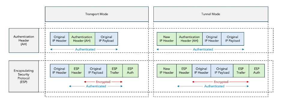
Figure 4: AH vs ESP and Transport Mode vs Tunnel Mode
In this tutorial we only discuss ESP tunnel mode, which is the most commonly deployed mode.
2.3.1 ESP Encapsulation
Figure 5 shows the format of an ESP packet.

Figure 5: ESP packet format
The ESP packet contains the following fields:
- The Security Parameter Index (SPI) is used to identify the Security Association (SA) to which the packet belongs.
- The Sequence Number is used to prevent replay attacks.
- Some encryption protocols require an Initialization Vector (IV).
- Padding may be present for two reasons: to implement Traffic Flow Confidentiality (TFC) and to align the ICV field to a 4-byte boundary.
- The Next Header indicates the protocol contained in the Original IP Payload (e.g. IPv4 or IPv6).
- The Integrity Check Value (ICV) is used to verify that packet was not modified and came from the claimed sender.
Most of the details of the ESP packet format are not important for this tutorial; what matters is that the communicating IPsec peers need to agree on two secret keys:
- An encryption key to encrypt the data covered by the red arrow (section 2.3.2).
- An authentication key to authenticate and integrity-protect the data covered by the blue arrow (section 2.3.3).
2.3.2 ESP Encryption
ESP uses symmetric encryption to encrypt part of the message payload, as indicated by the red arrow in figures 4 and 5 above.
The two communicating parties need to agree on:
- The symmetric encryption protocol, for example the Triple Data Encryption Standard (3DES) or the Advanced Encryption Standard (AES). This includes the protocol mode, for example AES Cipher Block Chaining (AES-CBC) or AES Galois / Counter Mode (AES-GCM).
- The key length, for example 128, 192, or 256 bits.
- The symmetric encryption key.
The encryption protocol and key length are allowed to be public information. The encryption key must be secret; it must only be known to the two communicating parties.
The IKEv2 control-plane protocol is used to negotiate the encryption protocol, key length, and key value.
2.3.3 ESP Authentication and Integrity Protection
The Integrity Check Value (ICV) in the ESP packet is used for:
- Integrity protection: verify that the contents of the IP packet were not modified in transit.
- Authentication: verify that the IP packet was actually sent by the claimed sender.
The IKEv2 control-plane protocol is used to negotiate which integrity protection protocol is used.
Most commonly, Hashed Message Authentication Codes (HMACs) are used for both integrity protection and authentication. In this case the ICV field contains a HMAC checksum over the secret authentication key combined with the fields covered by the blue arrow in Figure 4 and Figure 5 above.
This authentication key can be a configured Pre-Shared Key (PSK) or it can be dynamically negotiated by the IKEv2 protocol.
2.4 Security Associations (SAs)
The concept of a Security Association (SA) in IPsec refers to an agreement between two communicating peers on the set of parameters that are used to secure a particular flow of traffic.
These agreed-upon parameters include:
- The data-plane protocol (AH or ESP).
- The encryption algorithm (e.g. AES-256-CBC).
- The authentication method (pre-shared keys or certificates).
- The integrity algorithm, i.e. the hash algorithm for signing (e.g. SHA-256).
- The Diffie-Hellman group for key agreement (e.g. group 14).
There are typically multiple SAs between a pair of communicating IPsec peers. There is always one SA to secure the IKEv2 traffic itself. This is needed because some fields in the IKEv2 protocol are encrypted and authenticated. This SA is called the IKE SA.
There may be one or more additional SAs to secure the user-data encapsulated in ESP packets. These are called IPsec SAs. Each IPsec SA is associated with a particular flow of traffic, which is specified using Traffic Selectors (TSs) defined by an IP address range, an IP protocol ID, and a port range.
The IKE SA is bi-directional, but the IPsec SAs are uni-directional: there are separate IPsec SAs for each direction (inbound and outbound). In practice, IKEv2 always negotiates pairs of SAs, and the term “SA” is often used to refer to a pair of SAs.
The IKE SA is always the first SA that is created. This IKE SA is then used to negotiate the establishment of subsequent IPsec SAs. The IKE SA is called the parent SA, and the subsequent IPsec SAs are called child SAs.
Child SAs (both child IKE SAs and child IPsec SAs) are also created during rekeying, i.e. as a result of a rekeying.
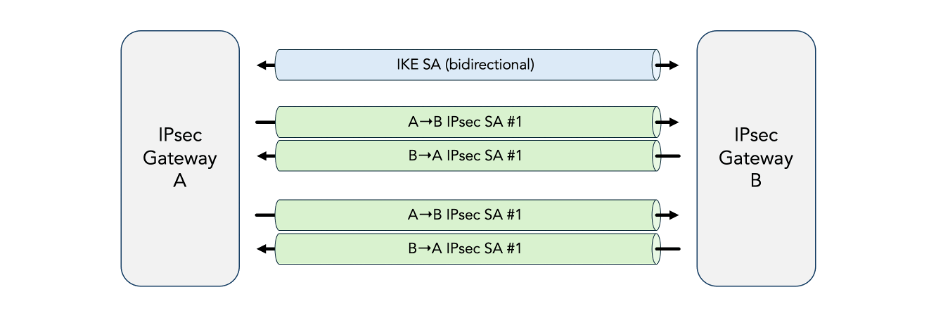
Figure 6: Security Associations (SAs)
2.5 Internet Key Exchange protocol version 2 (IKEv2)
The Internet Key Exchange protocol Version 2 (IKEv2) [RFC5996] is the IPsec control-plane protocol. It is responsible for:
- Authenticate communicating peers.
- Create and manage security associations.
- Negotiate the attributes of security associations (e.g. encryption keys).
IKEv2 is the successor to earlier IPsec control-plane protocols including the Internet Security Association and Key Management Protocol (ISAKMP) [RFC2408] and the Internet Key Exchange Protocol Version 1 (IKEv1) [RFC2409]. We don’t cover these older protocols in this tutorial since they do not support the PQC extensions.
2.5.1 IKEv2 Messages
IKEv2 messages are exchanged using User Datagram Protocol (UDP) packets. This has some consequences:
- Since UDP is unreliable, IKEv2 includes facilities (e.g. message IDs and retransmission timers) to detect and recover from transmission errors, including packet loss and duplication.
- When the UDP packets are larger than the path Message Transfer Unit (MTU) size, they are subject to IP fragmentation, which causes complications. For this reason, IKEv2 has its own fragmentation mechanism. This is particularly relevant for the PQC extensions to IPsec because the PQC keys tend to be large.
All messages in IKEv2 exist in pairs: a request and a response, which together form an exchange. For a given exchange, the side that sends the request is called the initiator and the side that sends the response is called the responder.
Each exchange is identified by a message ID. The initiator retransmits the request if it doesn’t receive the corresponding response within a time-out.
The most common exchange types used in IKEv2 are:
- IKE_SA_INIT and IKE_AUTH are always the first two message exchanged and are used to establish the initial IKE SA and IPsec SA.
- CREATE_CHILD_SA is used to establish additional child SAs for new traffic flows or for rekeying existing SAs.
- INFORMATIONAL are used to delete SAs, report error conditions, and other housekeeping.
Additional message types are defined in IPsec extension RFCs and I-Ds. Specifically, two new message types IKE_INTERMEDIATE and IKE_FOLLOWUP_KE are introduced by the PQC extensions.
All IKEv2 message start with a common header, shown in figure 7.
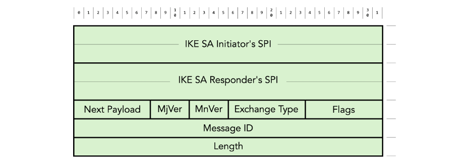
Figure 7: IKEv2 message header format
The header contains the following fields:
- The combination of the IKE SA initiator’s Security Parameter Index (SPI) and the IKE SA Responder’s SPI are used to identify the IKE SA.
- The Next Payload identifies the type of payload that follows the header in the IKEv2 message.
- MjVer and MnVer are the major and minor IKE protocol version respectively.
- Exchange Type identifies the type of exchange (IKE_SA_INIT, IKE_AUTH, CREATE_CHILD_SA, INFORMATIONAL, etc.)
- Message ID is used to match responses with requests and to control the retransmission of lost messages.
- There are various Flags, for example to indicate whether the message is a request or a response.
The IKEv2 message header is followed by zero or more payloads. Each payload starts with a generic payload header:

Figure 8: IKEv2 generic payload header format
The generic payload header contains the following fields:
- The Next Payload identifies the type of the next payload in the IKEv2 message (or 0 if there is no next payload).
- The Critical (C) flag is set to zero if the recipient can ignore the payload if it does not understand the payload type code.
There are many payload types. Table 1 below lists the payload types defined in the base IKEv2 RFC [RFC5996]. Additional payload types are defined in various extension RFCs and I-Ds.
| Next Payload Type | Notation | Value |
| No Next Payload | 0 | |
| Security Association | SA | 33 |
| Key Exchange | KE | 34 |
| Identification – Initiator | IDi | 35 |
| Identification – Responder | IDr | 36 |
| Certificate | CERT | 37 |
| Certificate Request | CERTREQ | 38 |
| Authentication | AUTH | 39 |
| Nonce | Ni, Nr | 40 |
| Notify | N | 41 |
| Delete | D | 42 |
| Vendor ID | V | 43 |
| Traffic Selector – Initiator | TSi | 44 |
| Traffic Selector – Responder | TSr | 45 |
| Encrypted and Authenticated | SK | 46 |
| Configuration | CP | 47 |
| Extensible Authentication | EAP | 48 |
Table 1: IKEv2 payload types
We are not going to describe the meaning and format of each payload in this tutorial. We will just describe the relevant payloads as we go through the examples.
2.5.2 Initial Exchange: establishment of the IKE SA and first IPsec SA
IKEv2 communications always begin with a so-called initial exchange, which normally consists of one IKE_SA_INIT exchange followed by one IKE_AUTH exchange, for a total of four IKEv2 messages. This is shown in figure 9 below.
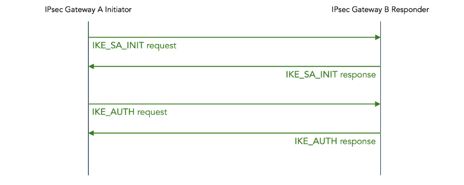
Figure 9: IKEv2 initial message exchange (normal case)
Figure 10 below shows the initial IKE_SA_INIT exchange in more detail.

Figure 10: IKEv2 initial IKE_SA_INIT exchange
The IKE_SA_INIT request contains the following payloads:
- Security Association initiates the negotiation of cryptographic algorithms for the IKE SA. It contains one or more proposals. Each proposal consists of a set of cryptographic algorithms (so-called transforms) that are acceptable to the initiator. In example below, IPsec Gateway A proposes two encryption algorithms (AES-128-CBC and 3DES), one pseudo-random function (HMAC-SHA1), one integrity algorithm (HMAC-SHA1-96), and one Diffie-Hellman group (group 2).
- Key Exchange initiates a Diffie-Hellman key exchange. The details of how a Diffie-Hellman exchange works are described in section 2.5.4 below.
- Nonce contains a random number that is mixed into keys derived from the Diffie-Hellman exchange to prevent replay attacks.
The IKE_SA_INIT response is similar to the IKE_SA_INIT request. The main difference is that the responder chooses a specific set of accepted cryptographic algorithms from the set of cryptographic algorithms proposed by the initiator. This concludes the negotiation.
The IKE_SA_INIT exchange is neither authenticated nor encrypted. The Diffie-Hellman exchange that takes place in the IKE_SA_INIT exchange establishes a shared secret that is used to derive keys that are used for authentication and encryption in the IKE_AUTH and subsequent messages.
The initial IKE_SA_INIT exchange is followed by an IKE_AUTH exchange, shown in figure 11 below. In this example a Pre-Shared Key (PSK) is configured for authentication; later we give another example using certificates for authentication.
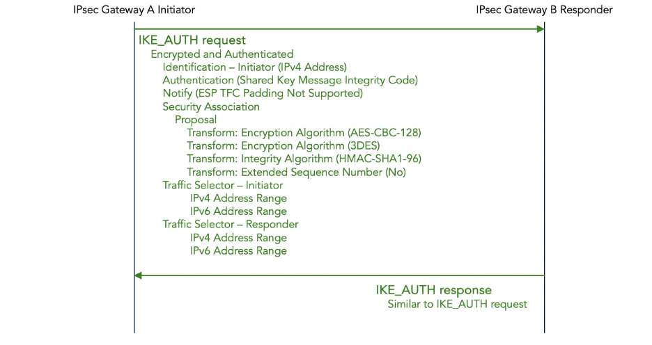
Figure 11: IKEv2 initial IKE_AUTH exchange — Pre-Shared Key (PSK) authentication
The IKE_AUTH request contains the following payloads:
- Identification – Initiator identifies the initiator, in this example using an IPv4 address.
- Authentication specifies which authentication method is used, in this case a Pre-Shared Key (PSK). It also contains the authentication data, in this case an HMAC code computed over the IKEv2 message, the pre-shared key, the nonce, and a value derived from the Diffie-Hellman shared secret.
- Notify payloads to negotiate features, in this example to report that Traffic Flow Confidentiality (TFC) padding is not supported.
- Security Association initiates the negotiation of cryptographic algorithms for the IPsec SA. Just as in the IKE_SA_INIT request, it consist of a set of proposals, each consisting of a set of transforms.
- Traffic Selector – Initiator and Traffic Selector – Responder combined contain a proposal for which traffic should flow through the IPsec tunnel. The traffic flows are described using IPv4 or IPv6 address ranges, port ranges, and protocols on the initiator and responder side respectively.
The payloads in the IKE_AUTH exchange are encrypted using the encryption method negotiated in the preceding IKE_SA_INIT exchange, and using an encryption key derived from the Diffie-Hellman shared secret.
Similarly, the payloads in the IKE_AUTH exchange are authenticated using the authentication method negotiated in the preceding IKE_SA_INIT exchange, and using an authentication key which is separately derived from the Diffie-Hellman shared secret.
We don’t show the details of the IKE_AUTH response, but it is similar to the IKE_AUTH request. Once again, the main difference is that the proposals are whittled down to specific choices.
2.5.3 Subsequent exchanges
After the initial IKE_SA_INIT and IKE_AUTH exchange, there may be CREATE_CHILD_SA exchanges to establish additional child SAs for new traffic flows or for rekeying existing SAs.
There may be INFORMATIONAL exchanges to delete SAs or to report error conditions or for other housekeeping.
Since the details of CREATE_CHILD_SA and INFORMATION exchanges are not relevant to post-quantum security, we don’t discuss them in this tutorial.
Later we will see that the IPsec PQC extensions introduce a new type of subsequent exchange, namely an INTERMEDIATE exchange.
2.5.4 IKEv2 Diffie-Hellman (DH) Key Exchange (KE)
IKEv2 uses the Diffie-Hellman algorithm to establish a shared secret between the two IPsec gateways. This shared secret is used to derive encryption and authentication keys.
The most important characteristic of the Diffie-Hellman algorithm is that an attacker cannot determine what the shared secret is even if she can observe all messages in the Diffie-Hellman exchange.
The Diffie-Hellman algorithm works as follows:

Figure 12: Diffie-Hellman Key Exchange
- IPsec gateways A and B agree to use two public (i.e. non-secret) parameters: the modulus p and the base g.
- IPsec gateway A picks a secret value a known only to A itself.
- IPsec gateway B picks a secret value b known only to B itself.
- IPsec gateway A publicly sends A = ga mod p to IPsec gateway B.
- IPsec gateway B publicly sends B = gb mod p to IPsec gateway A.
- IPsec gateway A computes shared secret Ba mod p = ga+b mod p = s.
- IPsec gateway B computes shared secret Ab mod p = ga+b mod p = s.
The IETF has standardized various good choices for values p and g and has assigned each standardized choice an identifier which is called the Diffie-Hellman (D-H) group number. The allocated D-H group numbers are documented in the IANA registry.
IKEv2 negotiates which Diffie-Hellman group to use (step 1) using the Diffie-Hellman group number transform in the Security Association payload in the IKE_SA_INIT exchange.
IKEv2 implements steps 4 and 5 by sending the public value A or B in the Key Exchange payload of the IKE_SA_INIT message.
The security of Diffie-Hellman relies on a type of mathematical function called a trapdoor function. This is a function which is easy to compute in one direction but very difficult to compute in the inverse direction. In the case of Diffie-Hellman, the trapdoor function is called exponentiation in a discrete field modulo a prime.
The two communicating parties do exponentiation in a discrete field; they compute A = ga mod p and B = gb mod p which can be done efficiently.
The inverse function is the logarithm in a discrete field modulo a prime.
An eavesdropper who observes the public values A and B being exchanged needs to compute logarithms in a discrete field to recover the secret values a and b. She needs to compute a = glog A mod p and b = glog B mod p. For large values of p this is computationally infeasible – it takes millions of years, even on a supercomputer.
There is a widely used variation of Diffie-Hellman (DH) called Elliptic Curve Diffie-Hellman (ECDH) which relies on elliptic curves instead of discrete exponentiation. We don’t discuss the details here.
2.5.5 Certificate-based authentication concepts
In addition to authentication using Pre-Shared Keys (PSKs), IKE2 also supports authentication using certificates and digital signatures.
Without getting too deep into the weeds of the very complex topic of Public Key Infrastructure (PKI), we provide a brief introduction to the concept of digital signatures. This is necessary because this is also one of the parts of IPsec that will turn out to be quantum-vulnerable.
Figure 13 below shows the process of digitally signing a message. The purpose of the digital signature is both authentication (verifying the identity of the sender) and integrity checking (verifying that the message was not changed).

Figure 13: Digital Signature Process
Digital signatures rely heavily on the concept of asymmetric encryption also known as a public-key cryptosystems. Unlike symmetric encryption, which uses one single key to both encrypt and decrypt messages, asymmetric encryption uses a pair of keys.
One key in the pair is called the private key (also known as the encapsulation key). It is secret, i.e., it is known only to one party. In figure 13 above, only the sender knows the private key.
The other key is the pair is called the public key (or sometimes decapsulation key). It is not secret, i.e., it is public. In figure 13 above, the receiver knows the public key, but anyone (including an attacker) is allowed to know it.
If a message is encrypted with the private key, it can only be decrypted with the public key. And, vice versa, if it can be decrypted with the public key, it must have been encrypted with the private key.
Before the sender can send signed messages to the receiver, they must first agree on which Digital Signature Algorithms (DSAs) to use and on a public / private key pair.
There are multiple standardized Digital Signature Algorithms, including the following which are described in detail in NIST Standard Digital Signature Standard (DSS) [FIPS 186-5]:
- Rivest-Shamir-Adleman (RSA)
- Digital Signature Algorithm (DSA) (deprecated)
- Elliptic Curve Digital Signature Algorithm (ECDSA)
- Edwards Curve Digital Signature Algorithm (EdDSA)
Each of these Digital Signature Algorithms is defined by:
- A key pair generation method.
- A signature generation method (encryption of the hash).
- A signature validation method (decryption of the hash).
IPsec uses the Authentication payload in the IKE_AUTH message to negotiate which Digital Signature Algorithm to use. That same authentication payload is also used to send the public key, encapsulated in a certificate to prove the binding between the public key and the identity (more details shortly).
Once the two speakers have agreed on which Digitial Signature Algorithm and which public / private key pair to use, the actual signing of messages works as follows:
- The sender generates a signature:
- The sender computes the hash over the sent message using the agreed-upon hash function.
- The sender encrypts the computed hash using the private key, which produces a signature.
- The sender sends both the message itself and the signature to the receiver.
- The receiver verifies the received signature:
- The receiver computes the hash over the received message using the same hash function. This gives a computed hash value.
- The receiver decrypts the received signature using the public key, which produces a received hash value.
- The receiver compares the computed hash value with the received (decrypted) hash value. If they mash, the validation succeeds, otherwise the validation fails.
If the validation succeeds, it proves (with high likelihood) two things to the receiver:
- Authentication: It proves that the sender of the message was in procession of the private key corresponding to the public key. This knowledge, combined with the use of certificates (which are explained below) also proves the identity of the sender.
- Integrity Protection: It proves that the message was not modified in transit.
The next question is: how does the receiver validate the identity of the sender? As alluded to above, we use certificates for this. The conceptual framework around certificates is called Public Key Infrastructure (PKI). This is a complex topic; here we only give a minimal basic introduction to understand how certificates are used in IPsec authentication.
A certificate is a proof that a particular public key belongs to a particular identity.
There are two parties involved in a certificate: the issuer and the signer. The issuer is the party whose public key is being associated with their identity. The signer is the party who digitally signs the certificate to prove that it is valid.
A certificate contains the following information:
- The identity of the issuer. This is stored in the Distinguished Name (DN) field. There are many ways to specify the identity. One way that is typically used in IPsec is the Common Name (CN) which is just a string chosen by the issuer.
- The public key of the issuer.
- The digital signature of the signer.
- There are many more fields in the certificate, which are too detailed for the present discussion (to give a random example: the date when the certificate expires).
Figure 14 summarizes how certificates and digital signatures are used to authenticate messages sent from a sending party (Alice) to a receiving party (Bob).

Figure 14: Authentication using certificates and digital signatures
We have two devices, Alice (in blue in the left) and Bob (in green on the right), where Alice wants to send authenticated messages to Bob. There is also an operator (in red at the top), which is the party who owns and operates the devices and who is responsible for configuring them.
Here we only discuss the mechanisms for Alice to authenticate her messages that she sends to Bob. Similar mechanisms are used for Bob to authenticate his messages sent to Alice (not shown here).
There are a number of steps that need to happen only once, at configuration time.
The operator needs a certificate and a private key that are used to authenticate the operator and that serve as the root of trust for all subsequent authentications.
In the case of IPsec, the operator typically acts as private Certificate Authority. This means that the operator itself generates a random public / private key pair, generates a certificate containing the operator’s identity and public key, and uses the generated private key to self-sign the certificate.
The operator installs the operator certificate on Bob, and configures Bob to accept the operator’s certificate as a root of trust. Later, we will see how Bob uses the operator’s certificate to verify the validity of Alice’s certificate.
The operator also configures the identity of Alice on Bob as a trusted identity and to allow the establishment of security associations with Alice (i.e. with any party who can prove that she has Alice’s identity).
We also need a certificate and private key for Alice. There are two methods to generate these.
The first method is for the operator to generate Alice’s public / private key pair, generate and sign Alice’s certificate, and then install Alice’s certificate and private key on the Alice device. The problem with this method is that the operator has knowledge of Alice’s private key. This is a security risk because whoever has access to Alice’s private key can pretend to be Alice.
The other method is for Alice herself to generate Alice’s public / private key pair. Alice then sends a Certificate Signing Request (CSR) to the operator. The operator signs the certificate using the operator’s private key, and sends the signed certificate back to the Alice device. This way, Alice’s private key never leaves Alices device. Alice’s device might have some sort of secure enclave to securely store the private key in such a manner that it can never leave the device.
The following steps happen in the initial IKE_AUTH exchange when the IKE SA is established, as shown in figure 15 below.

Figure 15: IKEv2 initial IKE_AUTH exchange — certificate authentication
The IKE_AUTH request message contains the following fields related to certificate-bases authentication:
- Certificate contains Alice’s certificate.
- Certificate Request requests Bob to send his certificate.
- Authentication contains the digital signature, generated using Alice’s private key.
- Identification contains Alice’s identity as reported in her certificate (typically her common name).
Bob checks the validity of Alice’s certificate using the operator’s certificate which was installed as the root of trust on Bob.
Once Alice’s certificate has been validated, Bob checks whether Alice’s identity has has been configured as a trusted security association peer.
Once Alice’s identity has been accepted, Bob stores Alice’s public key (extracted from Alice’s certificate). It will be used to validate messages received from Alice.
The following steps happen for each ESP packet that Bob receives from Alice:
- Alice generates a signature for the sent message using Alice’s private key.
- Alice sends the signature along with the message to Bob. In the case of ESP packets, the signature is sent in the Integrity Check Value (ICV) field.
- Bob validates the message signature using the public key in Alice’s certificate.
- If the signature validation passes, Bob knows that the message came from Alice and that the message was not modified in transit.
3 What is Post Quantum Cryptography (PQC) and why is it needed?
3.1 The threat of quantum computers
A new class of computers, called quantum computers, is currently under development by a large number of companies including IBM, Rigetti, IONQ, Quantinuum, Atom Computing, Alice & Bob, Xanadu, Alpine Quantum Technologies, Diraq, Infleqtion, IQM, Orca Computing, Oxford Ionics, Oxford Quantum Circuits, Pasqal, Planqc, PsiQuantum, Quantum Computing Inc., QuEra, Quandella, QuantWare, Quantum Brilliance, and others.
These quantum computers work in a fundamentally different way than all of the computers that we use today (desktops, laptops, mobile phones, mainframes, super computers, etc.), which we refer to as classical computers in this context.
Existing classical computers rely on bits, which are either zero or one. Quantum computers, on the other hand, use quantum bits (qubits). These qubits can in a certain sense be both zero and one at the same time. Quantum computers use special properties of quantum physics including superposition, interference and entanglement to perform calculations in a way that is fundamentally different from existing classical computers.
For the vast majority of applications, these quantum computers are much less powerful and much more expensive than existing classical computers. However, there is a handful of very specific algorithms for which quantum computers are vastly more powerful than classical computers.
One of these quantum computer algorithms is called Shor’s algorithm, which was discovered by mathematician Peter Shor in 1994. Shor’s algorithm enables a quantum computer to factor numbers and compute discrete logarithms in polynomial time complexity, whereas classical computers require exponential time complexity.
An exponential speedup is very significant. In practical terms, factoring large numbers (say 2048 bits) takes an infeasible amount of time (millions or billions of years) using the fastest classical algorithm currently know. A sufficiently powerful and reliable quantum computer able to run Short’s algorithm could reduce this to a practical amount of time (days, minutes, or even seconds).
Another quantum computer algorithm is called Grover’s algorithm, which was discovered by computer scientist Lov Grover in 1996. Grover’s algorithm enables a quantum computer to do a brute force search of unstructured data in an amount of time that scales as the square root of the number of searched items. With existing classical algorithms the search time scales linearly with the number of searched items.
This is polynomial speedup, which is impressive, but not as significant as an exponential speedup.
Both Shor’s algorithm and Grover’s algorithm need a sufficiently large and sufficiently reliable quantum computer to be able to run.
Sufficiently large means that it needs a large amount of quantum memory, i.e. a large number of quantum bits. The exact estimates vary and change over time, but it is going to be at least hundreds of thousands of qubits. Current commercially available quantum computers have no more than hundreds of (physical) qubits.
Sufficiently reliable covers a number of aspects:
- The quantum memories must reliably store the qubit values for a long time. Currently this is not yet the case. Current quantum memory hardware loses its state in somewhere between microseconds to seconds, depending on which hardware technology is used.
- The quantum gates must reliably perform operations on the qubits. Currently, this is also not yet the case. Currently, the error rates of quantum gates are somewhere in the range of 1% to 0.1%, which is much too high to write reliable quantum programs.
The term Noisy Intermediate Scale Quantum (NISQ) is used to refer to the current state-of-the-art in quantum computers. They are not yet very reliable (noisy) and not yet very large (intermediate scale).
Two approaches are being used to improve the quality of quantum computers to the point that they become useful (e.g., can run Shor and Grover):
- The hardware is improved to have longer memory storage times (“coherence times”) and lower error rates on the quantum gates.
- Fault-tolerant quantum computing. Here, multiple physical qubits are combined and protected with Quantum Error-Correction (QEC) to implement so-called logical qubits. The error-corrected logical quantum memories and error-corrected logical quantum gates will be reliably enough for implementing large-scale quantum algorithms such as Shor or Grover.
Despite the very large number of commercial companies and academic laboratories working on quantum computers, none of the publicly known quantum computers are fault tolerant or able to run Shor or Grover.
Just very recently, the first academic research groups and commercial companies have demonstrated early implementations of individual or very small numbers of logical qubits. Thus, we are at the stage that it has been demonstrated that fault tolerant quantum computing is possible, but much more engineering work is needed to scale this up to practically useful quantum computers. Opinions vary wildly on how much longer it will take to get there (we will say more about timelines later in section 3.5
3.2 Quantum-vulnerability of Diffie-Hellman key exchange
Traditional IPsec uses Diffie-Hellman to dynamically agree on encryption and authentication keys.
In section 2.5.4 we described how the security of Diffie-Hellman relies on the fact that it is computationally infeasible for a classical computer to compute the discrete logarithm for large numbers.
Once we have a sufficiently large and reliable quantum computer to run Shor’s algorithm, both Diffie-Hellman (DH) and Elliptic Curve Diffie-Hellman (ECDH) will be broken.
The term Cryptographically Relevant Quantum Computer (CRQC) is used to refer to a quantum computer that can break currently used quantum algorithms.
An adversary who is able to passively tap the traffic on an Internet link can:
- Observe the Diffie-Hellman or Elliptic Curve Diffie-Hellman exchange in IKEv2.
- Run Shor’s algorithm to determine the secret symmetric key value.
- Observe ESP packets and use this symmetric key to decrypt them.
Note that the adversary only needs the ability to passively monitor the traffic. No active man-in-the-middle attack is needed.
This opens Diffie-Hellman up to Harvest-Now Decrypt Later (HNDL) attacks. An adversary can record and store the traffic now, and decode it later, once a Cryptographically Relevant Quantum Computer (QRQC) becomes available. It is prudent to assume that national security agencies in various countries are already collecting traffic for later analysis by future quantum computers.
3.3 Quantum-vulnerability of certificate-based authentication
Certificate-based authentication relies on digital signature in two ways:
- Digital signatures are used to sign encrypted payload in IKEv2 and ESP messages.
- Digital signatures are used to sign certificates.
The Digital Signature Algorithms (DSA) that are currently in use are Rivest-Shamir-Adleman (RSA), Elliptic Curve Digital Signature Algorithm (ECDSA), and Edwards Curve Digital Signature Algorithm (EdDSA).
The security of all of these DSAs relies on the computational complexity of factoring numbers or discrete logarithms, and as a result, all of them are vulnerable to attack by a Cryptographically Relevant Quantum Computer (CRQC).
One important difference with the vulnerability of Diffie-Hellman, is that the digital signature algorithms are not vulnerable to a Harvest Now Decrypt Later (HNDL) type of attack. A quantum attack can only be a man-in-the-middle attack that must occur at the moment that the authentication takes place.
3.4 Quantum-vulnerability of symmetric encryption
The symmetric encryption algorithms, such as AES and 3DES are also vulnerable to attack by Cryptographically Relevant Quantum Computer (CRQC).
In this case, the vulnerability is due to Grover’s algorithm instead of Shor’s algorithm.
Consider that we are using a key-length of n bits. This means that there are 2n possible key values. A brute force attack by a classical computer involves a linear search of all possible key values, which has complexity O(2n). But a quantum computer capable of running Grover’s algorithm can do the search with time complexity O(√(2n)) = O(2n/2).
This is considered to be a much less severe problem than the quantum-vulnerability of Diffie-Hellman for the following two reasons.
First, the vulnerability is easily addressed simply by doubling the symmetric key sizes. For example, if you are currently using AES-128, you could switch to AES-256. A Grover attack against AES-256 has the same time complexity as a classical attack against EAS-128. One complication is that there is currently no standard for AES-512 (and coming up with such a standard is non-trivial). Thus, if you are currently using AES-256, you cannot easily double the key size.
Second, a classical brute-force attack against symmetric encryption is trivial to parallelize. It is easy to spread to work across a large number of processors simply by partitioning the key space. It seems that Grover’s algorithm is not easy to parallelize (link).
3.5 The urgency of making IPsec quantum-resistant
3.5.1 Technical considerations
Table 2 below summarizes the various aspects of IPsec that are vulnerable to attack by a Cryptographically Relevant Quantum Computer (CRQC). It also points out what the root-cause of the vulnerability is, how urgent addressing the vulnerability is, and what the remediation is.
| Aspect of IPsec | Quantum vulnerability | Vulnerable to HNDL | Urgency | Remediation |
| Diffie-Hellman key agreement | Shor’s algorithm. | Yes | Very high Start now | Deploy post-quantum IPsec as described in this tutorial. |
| Certificate-based authentication | Shor’s algorithm | No | Low | Deploy quantum-safe PKI when it becomes available. |
| Pre-Shared Key authentication | Grover’s algorithm | Yes | Low | Double key size if needed. |
| Symmetric encryption (AES) |
Table 2: Quantum-vulnerability of different aspects of IPsec
Remediating the quantum-vulnerability of Diffie-Hellman is the top priority due to Harvest Now Decrypt Later (HNDL). You should assume that state actors are already harvesting your IPsec traffic today. They will be able to retro-actively decrypt that IPsec traffic once a Cryptographically Relevant Quantum Computer (CRQC) becomes available. Estimates of when that will happen vary wildly, but 2030 seems to be a common estimate (link). If you IPsec tunnels are currently carrying traffic that needs to remain secret for more than that amount of time, you are already in trouble today. Deploying quantum-resistant IPsec, as described in this tutorial is most urgent for IPsec use cases that involve long-term confidentiality requirements (e.g. government, medical, military, high-value intellectual property, etc.)
Deploying quantum-resistant authentication is less urgent. Using Pre-Shared Keys (PSKs) is not a best security practice in the first place, but at least from a quantum-vulnerability point of view, you only need to consider doubling the key sizes, if that. Remediating the quantum-vulnerability of certificate-based authentic is a lower priority for two reasons. The first reason is that unlike key agreement, authentication is not vulnerable to HNDL. You have time until the CRQC actually exist to address the problem. The second reason is that the standardization and implementation of post-quantum PKI is far less mature than the standardization and implementation of post-quantum key agreement. It will still be a few years before the post-quantum PKI standards and implementations will be complete and stable.
Doing something about remediating the quantum-vulnerability of symmetric encryption (AES) and any other brute-force attacks is least urgent. If you are still using 128-bit symmetric keys, you could consider using 256-bit symmetric keys.
3.5.2 Regulatory considerations
Another consideration for the timeline of deploying quantum-resistant IPsec is regulatory compliance.
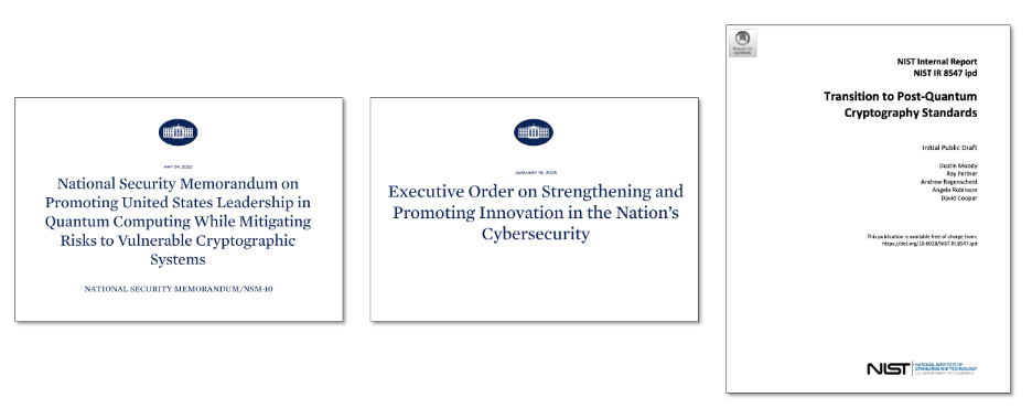
Figure 16: Post-quantum security regulatory compliance
On 4 May 2022 the United States government issued National Security Memorandum Number 10 on Promoting United States Leadership in Quantum Computing While Mitigating Risks to Vulnerable Cryptographic Systems. It sets a goal of transitioning to quantum-resistant cryptography by 2035:
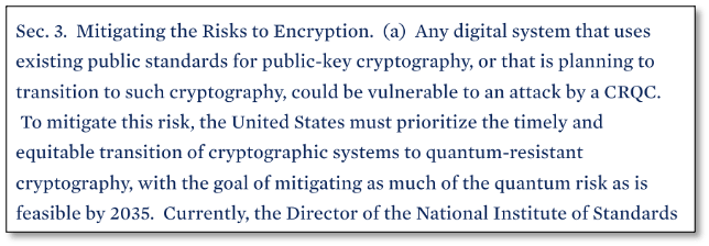
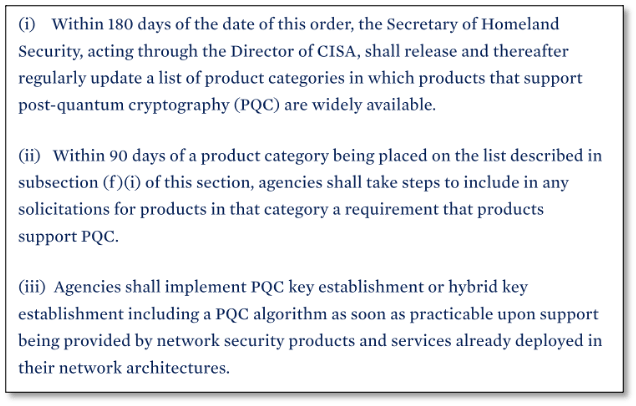
On 16 January 2025 the United States government issued an Executive Order on Strengthening and Promoting Innovation in the Nation’s Cybersecurity. It requires agencies include PQC in product requirements within 270 days and to deploy PQC algorithms “as soon as possible”.
In November 2024 NIST issued NIST Internal Report NIST IR 8547 (Initial Public Draft) Transition to Post-Quantum Cryptography Standards.
It identifies the following algorithms as being quantum-vulnerable:
- Key establishment: DH, ECDH, RSA
- Digital signatures: RSA, ECDSA, EdDSA
It proposes the following timelines for transitioning to quantum-resistant algorithms:
- 112-bit security strength: deprecated by 2030, disallowed by 2035
- 128-bit and higher security strength: disallowed by 2035
It continues to allow symmetric encryption providing at least 128 bits of classical security.
3.6 Approaches for making IPsec quantum-resistant
There are multiple different approach for making IPsec quantum-resistant, each with their pros and cons:
- Post Quantum Cryptography (PQC)
- Quantum Key Distribution (QKD)
- Distributed Symmetric Key Encryption (DSKE)
We briefly introduce each of these in more detail in the subsequent sections.
The main purpose of this tutorial is to describe in detail how to deploy, configure, and monitor IPsec using PQC on a commercially available firewall. We chose a Palo Alto firewall as an example, but other vendor also support PQC and work in a similar manner.
3.7 Post Quantum Cryptography (PQC)
Post-Quantum Cryptography (PQC) replaces the mathematical problem that are vulnerable to attack by quantum computers (factorization, discrete logarithms) with different mathematical problems that are believed to be secure against an attack by any computer, including a quantum computer.
The main advantage of PQC is that it can be implemented on classical hardware, often as a software upgrade on existing hardware platforms. Unlike QKD it does not need specialized quantum hardware. On very resource constrained platforms (e.g. Internet-of-Things devices or on smart-cards) it may be necessary to do a hardware upgrade because the PQC algorithms do need more processing and memory resources.
The main disadvantage of PQC is that there is no formal proof that the new mathematical problems are actually infeasible to solve on a quantum computer, or even on a classical computer for that matter. Despite many years of scrutiny, the standardized PQC algorithms have not been broken. But on the other hand, it took many years before Diffie-Hellman and RSA were found to be quantum-unsafe. And also, one of the candidates of the NIST post-quantum competition was found to be broken very late in the process (link).
3.8 Quantum Key Distribution (QKD)
Quantum Key Distribution (QKD) uses the quantum physical properties of individual photons (very weak pulses of light) to securely distribute keys in such a manner that any attempt to steal the key will be detected.
It is sometimes referred to as a physics-based approach (as opposed to a computational-complexity-based approach).
QKD is a relatively mature technology. For several years already, there have been multiple vendors that offer commercial QKD products, including: Toshiba, ID Quantique, Q*Bird, KEEQUANT, Quintessence Labs, QNu Labs, LuxQuanta, and Quantum Optics Jena.
For more details on QKD algorithms see webinar Protocols for Advanced Secure Protocols.
In July 2024 we already published another tutorial describing in detail how to deploy, configure, and monitor IPsec using QKD. That time we used a different vendor, namely Juniper Networks.
3.10 Hybrid quantum-resistance
Hybrid quantum-resistance refers to deploying multiple different quantum-resistant key agreement and/or authentication mechanisms:
- Combine a traditional algorithm (e.g. Diffie-Hellman, RSA, or ECDSA) with a PQC algorithm.
- Combine multiple PQC algorithms.
- Combine a PQC algorithm with QKD.
- All of the above.
In the case of key agreement, each participating key agreement method produces its own separate encryption key. The final encryption is key is created by using a Key Derivation Function (KDF) to somehow combine all the individual keys into a single key. One commonly used method is to XOR all keys with each other.
The resulting combined key is as strong as the strongest contributing key. In other words, all contributing key agreement methods must be broken to decrypt the traffic.
In the case of digital signatures, each signing algorithm produces a separate signature. Each signature needs to be separately generated and validated.
The advantages of hybrid schemes include:
- Defense in depth. The standards and implementations for the new quantum-resistant methods are very young and have not yet been scrutinized for many years. Algorithmic weaknesses in the standards and side-channel vulnerabilities in the implementation might yet be discovered. By combining multiple methods we are not putting all of our eggs in one basket.
- Regulatory compliance. Some standards (e.g. NIST FIPS 140
- Faster implementation. In some protocols (including IPsec) hybrid methods require fewer changes to the standards than pure quantum-resistant methods. This makes them easier to implement. In other protocols (PKI) it is the other way around.
Section 3.2.2. Hybrid Digital Signature Techniques in NIST Internal Report 8547 (Initial Public Draft) Transition to Post-Quantum Cryptography Standards section explicitly allows the use of hybrid schemes:
| Existing NIST standards and guidelines accommodate [the use of hybrid schemes] provided that at least one component digital signature algorithm is NIST-approved.” … NIST will accommodate the use of a hybrid key-establishment mode and dual signatures in FIPS 140 validation when suitably combined with a NIST-approved scheme. |
The disadvantages of hybrid schemes include:
- Increase resource usage:
- In the data-plane generating and validating multiple signatures costs extra processing cycles. This increases ASIC complexity. The throughput may decrease, or the latency may increase.
- In the control-plane exchanging multiple certificates increases CPU load and memory usage. This is a problem particularly for small embedded systems such as security cards and Internet of Things (IoT) devices, which have very limited resources.
- Using multiple digital signatures increases message sizes.
- In the data-plane, this increases the overhead on each message and decreases bandwidth efficiency.
- In the control-plane, this makes the protocol slower. If TCP window sizes are exceeded the slowdown may be dramatic because multiple round-trips are needed. When MTU sizes are exceeded, IP fragmentation tends to cause problems (IPsec has specific mechanisms to avoid these).
- In some protocols (e.g. PKI) support for hybrid schemes requires more complex changes in the standards, slowing down standardization, implementation, and adoption.
4 IPsec extensions for Post Quantum Cryptography (PQC)
In this section we describe how IPsec has been extended to support Post-Quantum Cryptography (PQC).
4.1 Module-Lattice-based Key Encapsulation Method (ML-KEM)
Before we discuss the extensions to IPsec itself, we first discuss the new quantum-resistant PQC key exchange algorithms that replace the quantum-vulnerable Diffie-Hellman key exchange algorithm.
Back in 2016, the National Institute of Standards and Technology (NIST) started a program and competition for standardizing PQC.
Eight years later, on August 13, 2024, out of the 70 candidate algorithms submitted in the first round, NIST released the first three PQC standards:
- FIPS 203: Module-Lattice-Based Key-Encapsulation Mechanism (ML-KEM), based on its predecessor CRYSTALS-Kyber.
- FIPS 204: Module-Lattice-Based Digital Signature (ML-DSA) based on its predecessor CRYSTALS-Dilithium.
- FIPS 205: Stateless Hash-Based Digital Signature (SLH-DSA) based on its predecessor SPHINCS+.
The first of these three standards (ML-KEM) is a quantum-resistant Key Exchange Mechanism (KEM) that can be used to replace the quantum-vulnerable Diffie-Hellman algorithm.
The other two standards (ML-DSA and SLH-DSA) are Digital Signature Algorithms (DSAs) which are used for other purposes.
We prepared this tutorial using PAN-OS version 11.2.3-h3 which did not yet support ML-KEM, but it did support its predecessor Kyber as well as several other PQC algorithms that have not (yet) been standardized: Bike, Classic Mceliece, FrodoKEM, HQC, and NTRU Prime.
4.2 Generalizing the Key Exchange (KE)
RFC9370 “Multiple Key Exchanges in the Internet Key Exchange Protocol Version 2 (IKEv2)” describes how IPsec has been extended to support additional key exchange methods beyond Diffie-Hellman.
So far, the only standardized quantum-resistant key exchange method is ML-KEM but will be standardized in the future. Also, vendors (including Palo Alto) support pre-standard PQC Key Exchange Methods such as CRYSTALS-Kyber (Palo Alto uses Unassigned Transform ID 1080 for this).
RFC9370 renames Transform type 4 from “Diffie-Hellman Group” to “Key Exchange Method (KE)”.
It also renames an IANA registry for this Transform Type from “Transform Type 4 – Diffie-Hellman Group Transform IDs” to “Transform Type 4 – Key Exchange Method Transform IDs”.
And it allocates new three Transform Type 4 code points for the PQC Key Exchange Methods ML-KEM-512, ML-KEM-768, and ML-KEM-1024.
Note that this change is backwards compatible: IPsec implementations that have not yet implemented the PQC extensions can interoperate with IPsec implementation that have implemented the PQC extensions, using a Diffie-Hellman key exchange.
4.3 ML-KEM Key Exchange
All Key Exchange Methods exchange some public data that allow the two parties to agree on a shared secret. This public data is carried in the Key Exchange Data field in the Key Exchange payload.
The contents of the Key Exchange Data depend on the Key Exchange Method.
For Diffie-Hellman, the Key Exchange Data field contains the public values A or B described in section 2.5.3.
Internet Draft draft-kampanakis-ml-kem-ikev2 (Post-quantum Hybrid Key Exchange with ML-KEM in the Internet Key Exchange Protocol Version 2 (IKEv2)) describes how to generate the public value in the Key Exchange Data field for ML-KEM:
- ML-KEM generates a pair of keys: the public / encapsulation key pk and the private / decapsulation key sk.
- The initiator sends the public key pk to the responder in the Key Exchange Data field.
- The responder “encapsulates the received public key pk“. This produces two values: a ciphertext ct and a shared secret ss.
- The responder sends the ciphertext ct back to the initiator in a Key Exchange Data field.
- The initiator “decapsulates the received ciphertext ct“, using its private / decapsulation key sk. This produces the same shared secret ssthat the responder has.

Figure 17: ML-KEM Key Exchange Method
4.4 IKEv2 Message Fragmentation
RFC7383: Internet Key Exchange Protocol Version 2 (IKEv2) Message Fragmentation introduced the concept of fragmentation at the IKE message level for the following reasons (quoting the RFC):
| IKEv2 uses UDP as a transport for its messages. Most IKEv2 messages are relatively small, usually below several hundred bytes. A notable exception is the IKE_AUTH exchange, which requires fairly large messages, up to several KB, especially when certificates are transferred. When the IKE message size exceeds the path MTU, it gets fragmented at the IP level. The problem is that some network devices, specifically some NAT boxes, do not allow IP fragments to pass through. This apparently blocks IKE communication and, therefore, prevents peers from establishing an IPsec Security Association (SA). … The solution to the problem […] is to perform fragmentation of large messages by IKEv2 itself and replace them with a series of smaller messages. In this case, the resulting IP datagrams will be small enough so that no fragmentation at the IP level will take place. |
The public information exchanged for ML-KEM (namely pk and ct) and other PQC key exchange methods tends to be larger than typical network MTUs (1500 bytes) and hence do not fit in an unfragmented UDP packet.
Because of this, we need IKEv2 Message Fragmentation to be able to carry PQC data in the Key Exchange Data field.
4.5 Intermediate Exchanges
Unfortunately, IKEv2 cannot be used to fragment the initial IKE_SA_INIT message, only to fragment messages after that. This is a problem because the Key Exchange Data field with PQC data is normally in the IKE_SA_INIT message.
We use the following two standards to get around this problem:
- RFC9242: Intermediate Exchange in the Internet Key Exchange Protocol Version 2 (IKEv2)
- RFC 9370: Multiple Key Exchanges in the Internet Key Exchange Protocol Version 2 (IKEv2)
Two RFCs enable IPsec to send the large Key Exchange Data fields for PQC Key Exchange Methods in separate IKE_INTERMEDIATE messages after the IKE_SA_INIT message when an IKE SA is first established. When an IKE SA is rekeyed or when additional child SAs are established, the large Key Exchange Data fields are carried in IKE_FOLLOWUP_KE messages.
Since both the IKE_INTERMEDIATE and the IKE_FOLLOWUP_KE message sent after the IKE_SA_INIT message, they can be IKEv2 fragmented.
4.6 Multiple Key Exchange Methods (KEMs)
In addition to moving the Key Exchange Data to a separate message, RFC9370 also introduces concept of using multiple Key Exchange Methods, each producing its own secret key. The final secret key is created by combining these secret keys and is as strong as the strongest contributing individual key.
The PQC Key Exchange Methods (ML-KEM and the pre-standard ones) are relatively young. While PQC algorithms and their implementations have been publicly scrutinized, they have not been scrutinized to the same extent as classical algorithms such as Diffie-Helman and RSA. There is still a lingering concern that specific PQC algorithms could have undiscovered weaknesses in either the algorithm itself or in a specific implementation. This is not a theoretical concern – both have happened. One of the round-4 finalists in the NIST PQC competition (Super-singular Isogeny Key Encapsulation (SIKE)) turned out the be easily broken, not just by a quantum computer but even by a modest classical laptop (link). And researchers found a side-channel attack against an implementation of CRYSTALS-Kyber that was supposed to be side-channel resistant.
Having support for multiple Key Exchange Method in IKEv2 buys us two things:
- By still including Diffie-Hellman as one of the contributing Key Exchange Methods, in addition to the PQC Key Exchange Methods, we guarantee that the final key no weaker than a Diffie-Hellman generated key alone. In other words, we are no worse off than we were before PQC. This also helps with regularly compliance.
- If we use multiple PQC Key Exchange Methods (some pre-standard ones in addition to ML-KEM) we increase security. The adversary would have break all contributing PQC algorithms to break the final key. Just breaking one or a few of PQC algorithms is not enough.
To support multiple Key Exchange Methods, IKEv2 introduces seven new proposal transform types: Additional Key Exchange 1 (ADDKE1) through Additional Key Exchange 7 (ADDKE7).
As a result, IKEv2 can create a composite key by combining key from up to 8 key exchanges.
The Key Exchange Data for the traditional (i.e., non-additional) key exchange (which is typically still a Diffie-Hellman key exchange) is carried in the same place where it was carried before the introduction of PQC, namely in the Key Exchange payload of the IKE_SA_INIT message itself.
But the Key Exchange Data for the additional key exchanges (which are typically PQC key exchanges) are carried in Key Exchange payloads in separate IKE_INTERMEDIATE messages after the IKE_SA_INIT message. Because the Key Exchange Data is usually bigger than the MTU, these IKE_INTERMEDIATE messages are typically IKEv2 message fragmented.
4.7 PQC key exchange in IPsec: an example
Now that we have covered all the pieces of the protocol, we can finally give a complete example of IKEv2 exchanges a PQC key.
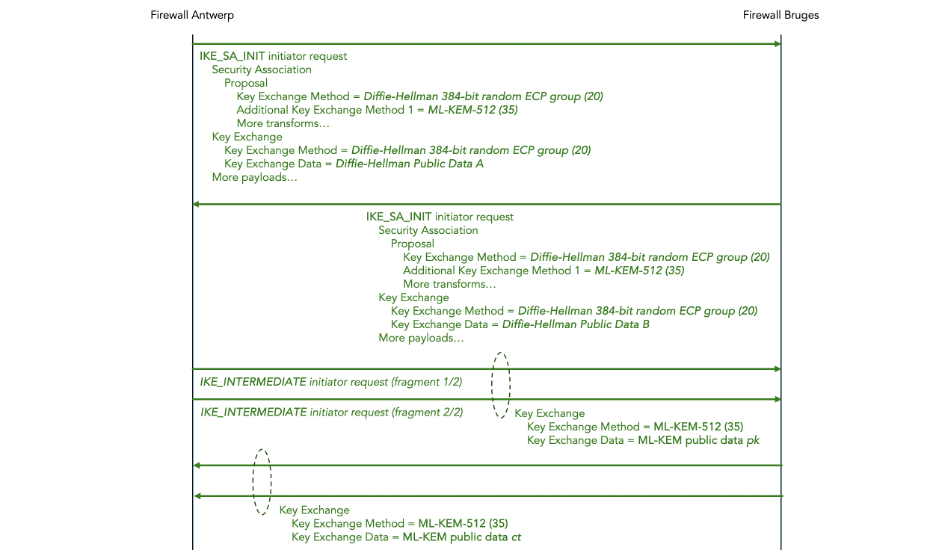
Figure 18: ML-KEM Key Exchange in IKEv2
In the IKE_SA_INIT messages, both the initiator and the responder propose two Key Exchange Methods: a Diffie-Hellman 384-bit random ECP exchange and additionally an ML-KEM-512 exchange.
The public data for Diffie-Hellman is sent in the Key Exchange payload in the same IKE_SA_INIT message.
The public data for ML-KEM is sent in the Key Exchange payload in follow-up IKE_INTERMEDIATE messages.
Since the ML-KEM public data is large, those IKE_INTERMEDIATE messages are IKEv2 message fragmented.
4.8 Making IPsec authentication quantum-resistant
So far, we have discussed making IPsec key exchange quantum-resistant using ML-KEM instead of (or, more typically, in addition to) Diffie-Hellman.
In addition to key exchange, we also need to make authentication quantum-resistant.
IKEv2 uses IKE_AUTH messages to negotiate the authentication method.
One possible authentication method is pre-shared keys. Here, we are speaking of the authentication keys, not to be confused with encryption keys. Pre-shared keys are quantum-resistant (assuming they are rotated frequently enough) but they are clumsy, difficult to manage, and difficult to scale.
The other possible authentication method is digital signatures using public key cryptography such as Rivest Shamir Adleman (RSA), Digital Signature Algorithm (DSA), or Elliptic Curve DSA (ECDSA). All these methods use a pair of keys: one public key and one private key. The sender digitally signs messages using the private key, and the receiver verifies the digital signature using the public key.
RSA, DSA, and ECDSA are quantum-vulnerable: they all rely on the computational complexity of mathematical problems that are vulnerable to being broken by quantum computers due to Shor’s algorithm.
The solution is to use a quantum-resistant Digital Signature Algorithm (DSA) instead. So far, NIST has standardized two PQC DSAs, namely FIPS 204 Module-Lattice-Based Digital Signature Algorithm (ML-DSA) and FIPS 205 Sateless Hash-Based Digital Signature Algorithm (SH-DSA).
However, at the time of writing of this blog (January 2025), the IETF is still in the process of finalizing the standards for incorporating these new NIST algorithms into PKI, and implementations are not yet as mature and the implementations of PQC key agreement.
There is a general consensus that making IKEv2 key agreement quantum-resistant is more urgent than making IKEv2 authentication quantum-resistant.
IKEv2 key agreement is vulnerable to Harvest Now Decrypt Later (HNDL) attack. An adversary could record and store IPsec messages. Later, when a Cryptographically Relevant Quantum Computer (CRQC) becomes available, the adversary could use Shor’s algorithm to analyze the recorded Diffie-Hellman exchange, extract the shared secret (symmetric encryption key), and decrypt the ESP traffic. Thus, we must make IKEv2 key agreement quantum-resistant now to prevent HNDL attacks in the future.
IKEv2 authentication is not vulnerable to HNDL attacks. If an adversary wants to break authentication to launch a man-in-the-middle attack, he must use Shor’s algorithm to break RSA / DSA / ECDSA and extract the private authentication key right there and then. This is not a concern for the future; this works if a CRQC that can work in real-time is already available.
4.9 Making symmetric encryption more quantum-resistant
The final part of IPsec that should be enhanced to make it more quantum-resistant is the symmetric encryption in the IPsec Encapsulating Security Payload (ESP).
Two communicating IPsec parties negotiate which symmetric encryption protocol and which key size to use to encrypt the ESP payload. The Advanced Encryption Standard (AES) [FIPS-197] is a very common choice for the encryption protocol. IPsec supports AES key sizes 128, 192, and 256. Key size 128 is the default and a common choice.
Symmetric encryption is also vulnerable to attack by quantum computers: not due to Shor’s algorithm but due to Grover’s algorithm. Grover’s algorithm provides only a quadratic speedup, unlike Short’s algorithm which provides an exponential speedup.
In theory this means that all symmetric key sizes should be doubled to maintain the same level of security in the face of quantum computers. If you currently use AES-128, you should switch to AES-256. Note that this does not require any new features in IPsec or any software upgrade.
But if you currently use AES-192 or AES-256, there is an issue: there is currently no NIST standard for AES-512 and there are reasons why creating a standard for AES-512 is non-trivial (see this link).
This is not as bad as it sounds. The general consensus is that in actual practice, implementations of Grover’s algorithm (once a sufficiently powerful quantum computer actually exists) will not actually be quadratically faster than current classical algorithms. This is because current brute force classical attacks are very well parallelizable (i.e. the work can be spread out over a very large number of processors running in parallel) whereas Grover’s algorithm does not parallelize well (see this link).
5 Hands-on tutorial for configuring PQC IPsec on Palo Alto firewalls
5.1 Conventions for configuration instructions
In the remainder of this document, we give a hands-on tutorial on how to configure a PQC IPsec tunnel on a pair of Palo Alto firewalls.
We use the following conventions in the configuration instructions.
A yellow box indicates a command to enter in your computer’s shell. We are using zsh om macOS, but any Linux-like shell should do:
$ date
Sun Jul 14 08:34:52 CST 2024
We assume that the following environment variables are set in the shell. In the instructions below, we will indicate where to get the values for these environment variables.
| Environment variable | Value |
| PALO_ALTO_ANTWERP_IP | The AWS elastic IP address associated with the AWS instance running Palo Alto Antwerp. |
| PALO_ALTO_BRUGES_IP | The AWS elastic IP address associated with the AWS instance running Palo Alto Bruges. |
| PALO_ALTO_SSH_KEY | The full path of the file which contains the private key to SSH the Palto Alto instances. |
A blue box indicates a command to enter in the PAN-OS Command Line Interface (CLI) of firewall Antwerp:
admin@PA-VM> show clock
Sat Dec 28 00:21:24 PST 2024
A green box indicates a command to enter in the CLI of firewall Bruges:
admin@PA-VM> show cli idle-timeout

Idle timeout for this session is 60 minutes
Remaining time for this session is 60 minutes 0 seconds
5.2 Deploy the Palo Alto firewalls in AWS
The first step is to create the various resources in AWS for the scenario shown in Figure 19 below:
- A Virtual Private Cloud (VPC) named palo-alto-vpc.
- One EC2 instance for each of the two Palo Alto VM-Series firewalls: palo-alto-antwerp and palo-alto-bruges.
- Subnet palo-alto-mgmt for the management network.
- Subnet palo-alto-untrust for the untrusted network between the two firewalls.
- An elastic IP address for the management interface on each of the two firewalls.
- An Internet Gateway (IG) to connect the management interface to the public Internet.
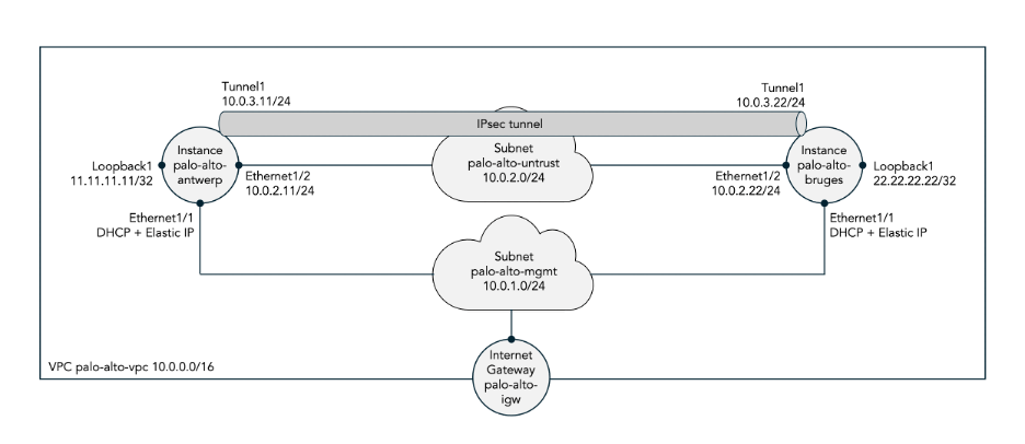
Figure 19: Two Palo Alto firewalls hosted in AWS
In appendix A we describe how to manually configure these resources using the AWS console. Doing this manually is a good learning experience but tedious and error-prone. In production deployments one would use something like AWS CloudFormation or TerraForm to automate the deployment.
5.3 Configure the IPsec tunnel using traditional Diffie-Hellman key exchange
First, we configure an IPsec tunnel between the two firewalls using traditional Diffie-Hellman generated keys, i.e. not yet using PQC generated keys. This allows us to verify that the firewalls are up and running, properly configured, and that traffic can flow through the IPsec tunnel before we complicate matters by bringing PQC into the picture.
We use the PAN-OS Command Line Interface (CLI) to configure the IPsec tunnels. Each of the following commands is to be entered in the configuration mode of PA-OS. Once all configuration commands have been entered, you need to commit them. It is also possible to use the web interface to configure the IPsec tunnels (including adding PQC later on) but we don’t show that in this tutorial.
Set the hostname:
set deviceconfig system hostname antwerp
set deviceconfig system hostname bruges
Assign an IP address to interface ethernet1/1:
set network interface ethernet ethernet1/1 layer3 ip 10.0.2.11/24
set network interface ethernet ethernet1/1 layer3 ip 10.0.2.22/24
Assign an IP address to interface loopback.1:
set network interface loopback units loopback.1 ip 11.11.11.11/32
set network interface loopback units loopback.1 ip 22.22.22.22/32
Assign a management profile to each interface to allow pings:
set network profiles interface-management-profile MGMT-PROFILE ping yes
set network interface ethernet ethernet1/1 layer3 interface-management-profile MGMT-PROFILE
set network interface loopback units loopback.1 interface-management-profile MGMT-PROFILE
set network interface tunnel units tunnel.1 interface-management-profile MGMT-PROFILE
set network profiles interface-management-profile MGMT-PROFILE ping yes
set network interface ethernet ethernet1/1 interface-management-profile MGMT-PROFILE
set network interface loopback units loopback.1 interface-management-profile MGMT-PROFILE
set network interface tunnel units tunnel.1 interface-management-profile MGMT-PROFILE
Assign zones to each interface:
set zone UNTRUST-ZONE network layer3 ethernet1/1
set zone TRUST-ZONE network layer3 loopback.1
set zone VPN-ZONE network layer3 tunnel.1
set zone UNTRUST-ZONE network layer3 ethernet1/1
set zone TRUST-ZONE network layer3 loopback.1
set zone VPN-ZONE network layer3 tunnel.1
Configure the inter-zone policies:
set rulebase security rules TRUST-TO-UNTRUST-RULE from TRUST-ZONE to UNTRUST-ZONE source any destination any application any service any action allow
set rulebase security rules TRUST-TO-VPN-RULE from TRUST-ZONE to VPN-ZONE source 11.11.11.11/32 destination 22.22.22.22/32 application any service any action allow
set rulebase security rules VPN-TO-TRUST-RULE from VPN-ZONE to TRUST-ZONE source 22.22.22.22/32 destination 11.11.11.11/32 application any service any action allow
set rulebase security rules TRUST-TO-UNTRUST-RULE from TRUST-ZONE to UNTRUST-ZONE source any destination any application any service any action allow
set rulebase security rules TRUST-TO-VPN-RULE from TRUST-ZONE to VPN-ZONE source 22.22.22.22/32 destination 11.11.11.11/32 application any service any action allow
set rulebase security rules VPN-TO-TRUST-RULE from VPN-ZONE to TRUST-ZONE source 11.11.11.11/32 destination 22.22.22.22/32 application any service any action allow
Assign the interfaces to a virtual router:
set network virtual-router VIRT-RTR interface [ ethernet1/1 loopback.1 tunnel.1 ]
set network virtual-router VIRT-RTR interface [ ethernet1/1 loopback.1 tunnel.1 ]
Configure the IPsec IKE gateway:
set network ike gateway IKE-GATEWAY protocol version ikev2
set network ike gateway IKE-GATEWAY protocol ikev2
set network ike gateway IKE-GATEWAY protocol ikev2 ike-crypto-profile default
set network ike gateway IKE-GATEWAY authentication pre-shared-key key SECRET-KEY
set network ike gateway IKE-GATEWAY peer-address ip 10.0.2.22
set network ike gateway IKE-GATEWAY local-address interface ethernet1/1
set network ike gateway IKE-GATEWAY protocol version ikev2
set network ike gateway IKE-GATEWAY protocol ikev2
set network ike gateway IKE-GATEWAY protocol ikev2 ike-crypto-profile default
set network ike gateway IKE-GATEWAY authentication pre-shared-key key SECRET-KEY
set network ike gateway IKE-GATEWAY peer-address ip 10.0.2.11
set network ike gateway IKE-GATEWAY local-address interface ethernet1/1
Configure the IPsec tunnel:
set network tunnel ipsec IPSEC-TUNNEL auto-key ike-gateway IKE-GATEWAY
set network tunnel ipsec IPSEC-TUNNEL auto-key ipsec-crypto-profile default
set network tunnel ipsec IPSEC-TUNNEL tunnel-interface tunnel.1
set network tunnel ipsec IPSEC-TUNNEL auto-key ike-gateway IKE-GATEWAY
set network tunnel ipsec IPSEC-TUNNEL auto-key ipsec-crypto-profile default
set network tunnel ipsec IPSEC-TUNNEL tunnel-interface tunnel.1
Configure a static route for the remote loopback pointing into the IPsec tunnel:
set network virtual-router VIRT-RTR routing-table ip static-route TO-BRUGES-ROUTE destination 22.22.22.22/32 interface tunnel.1
set network virtual-router VIRT-RTR routing-table ip static-route TO-ANTWERP-ROUTE destination 11.11.11.11/32 interface tunnel.1
The end result of these configuration commands should be the following configuration. We only show the part of the configuration that we ourselves added plus the IPsec default profiles. Also, we only show the final configuration for firewall Antwerp; the configuration for firewall Bruges is very similar.
deviceconfig {
  system {
    hostname antwerp;
  }
}
network {
  interface {
    ethernet {
      ethernet1/1 {
        layer3 {
          ip {
            10.0.2.11/24;
          }
          interface-management-profile MGMT-PROFILE;
        }
      }
    }
    loopback {
      units {
        loopback.1 {
          ip {
            11.11.11.11/32;
          }
          interface-management-profile MGMT-PROFILE;
        }
      }
    }
    tunnel {
      units {
        tunnel.1 {
          interface-management-profile MGMT-PROFILE;
        }
      }
    }
  }
  profiles {
    interface-management-profile {
      MGMT-PROFILE {
        ping yes;
      }
    }
  }
  ike {
    crypto-profiles {
      ike-crypto-profiles {
        default {
          encryption [ aes-128-cbc 3des];
          hash sha1;
          dh-group group2;
          lifetime {
            hours 8;
          }
        }
        Suite-B-GCM-128 {
          encryption aes-128-cbc;
          hash sha256;
          dh-group group19;
          lifetime {
            hours 8;
          }
        }
        Suite-B-GCM-256 {
          encryption aes-256-cbc;
          hash sha384;
          dh-group group20;
          lifetime {
            hours 8;
          }
        }
      }
      ipsec-crypto-profiles {
        default {
          esp {
            encryption [ aes-128-cbc 3des];
            authentication sha1;
          }
          dh-group group2;
          lifetime {
            hours 1;
          }
        }
        Suite-B-GCM-128 {
          esp {
            encryption aes-128-gcm;
            authentication none;
          }
          dh-group group19;
          lifetime {
            hours 1;
          }
        }
        Suite-B-GCM-256 {
          esp {
            encryption aes-256-gcm;
            authentication none;
          }
          dh-group group20;
          lifetime {
            hours 1;
          }
        }
      }
    }
    gateway {
      IKE-GATEWAY {
        protocol {
          version ikev2;
          ikev2 {
            ike-crypto-profile default;
            ikev2-fragment {
              enable yes;
            }
            pq-kem {
              enable yes;
              block-vulnerable-cipher yes;
            }
            pq-ppk {
              enabled no;
              negotiation-mode preferred;
            }
            dpd {
              enable no;
            }
          }
          ikev1 {
            dpd {
              enable no;
            }
          }
        }
        authentication {
          pre-shared-key {
            key -AQ==WeZTNpxFiwkjboqhOTmFh5cA3VI=F154Qe6FztgnnzZga/VUbQ==;
          }
        }
        peer-address {
          ip 10.0.2.22;
        }
        local-address {
          interface ethernet1/1;
        }
        protocol-common {
          nat-traversal {
            enable no;
          }
          fragmentation {
            enable no;
          }
        }
      }
    }
  }
  virtual-router {
    VIRT-RTR {
      interface [ ethernet1/1 loopback.1 tunnel.1];
      routing-table {
        ip {
          static-route {
            TO-BRUGES-ROUTE {
              destination 22.22.22.22/32;
              interface tunnel.1;
            }
          }
        }
      }
    }
  }
  tunnel {
    ipsec {
      IPSEC-TUNNEL {
        auto-key {
          ike-gateway {
            IKE-GATEWAY;
          }
          ipsec-crypto-profile default;
        }
        tunnel-interface tunnel.1;
      }
    }
  }
}
zone {
  UNTRUST-ZONE {
    network {
      layer3 ethernet1/1;
    }
  }
  TRUST-ZONE {
    network {
      layer3 loopback.1;
    }
  }
  VPN-ZONE {
    network {
      layer3 tunnel.1;
    }
  }
}
rulebase {
  security {
    rules {
      TRUST-TO-UNTRUST-RULE {
        from TRUST-ZONE;
        to UNTRUST-ZONE;
        source any;
        destination any;
        application any;
        service any;
        action allow;
      }
      TRUST-TO-VPN-RULE {
        from TRUST-ZONE;
        to VPN-ZONE;
        source 11.11.11.11/32;
        destination 22.22.22.22/32;
        application any;
        service any;
        action allow;
      }
      VPN-TO-TRUST-RULE {
        from VPN-ZONE;
        to TRUST-ZONE;
        source 22.22.22.22/32;
        destination 11.11.11.11/32;
        application any;
        service any;
        action allow;
      }
    }
  }
}
5.4 Verify that the IPsec tunnel (using Diffie-Hellman keys) comes up
Perform the following show commands on to verify that everything is working as expected, in particular that the IPsec tunnel comes up and forwards traffic.
On firewall Antwerp, verify that interface ethernet1/1 is up:
admin@antwerp> show interface ethernet1/1

--------------------------------------------------------------------------------
Name: ethernet1/1, ID: 16
Link status:
  Runtime link speed/duplex/state: ukn/ukn/up
  Configured link speed/duplex/state: auto/auto/auto
MAC address:
  Port MAC address 06:cc:bd:6a:ad:b1
Interface Type :
  Port Type: RJ45
Operation mode: layer3
Untagged sub-interface support: no
--------------------------------------------------------------------------------
Name: ethernet1/1, ID: 16
Operation mode: layer3
Virtual router VIRT-RTR
Interface MTU 1500
Interface IP address: 10.0.2.11/24
Interface management profile: MGMT-PROFILE
  ping: yes  telnet: no  ssh: no  http: no  https: no
  snmp: no  response-pages: no  userid-service: no
Service configured: IKE
Zone: UNTRUST-ZONE, virtual system: vsys1
Adjust TCP MSS: no
Ignore IPv4 DF: no
Policing: no
Proxy protocol: no
... more ...
Do the same on firewall Bruges: verify that interface ethernet is up:
admin@bruges> show interface ethernet1/1

--------------------------------------------------------------------------------
Name: ethernet1/1, ID: 16
Link status:
  Runtime link speed/duplex/state: ukn/ukn/up
  Configured link speed/duplex/state: auto/auto/auto
MAC address:
  Port MAC address 06:f0:c0:f7:f4:65
Interface Type :
  Port Type: RJ45
Operation mode: layer3
Untagged sub-interface support: no
--------------------------------------------------------------------------------
Name: ethernet1/1, ID: 16
Operation mode: layer3
Virtual router VIRT-RTR
Interface MTU 1500
Interface IP address: 10.0.2.22/24
Interface management profile: MGMT-PROFILE
  ping: yes  telnet: no  ssh: no  http: no  https: no
  snmp: no  response-pages: no  userid-service: no
Service configured: IKE
Zone: UNTRUST-ZONE, virtual system: vsys1
Adjust TCP MSS: no
Ignore IPv4 DF: no
Policing: no
Proxy protocol: no
--------------------------------------------------------------------------------
... more ...
At this point, there are probably no IPsec security associations yet, because by default the IPsec tunnel only comes up when traffic flows through it:
admin@bruges> show vpn ike-sa

There is no IKEv1 phase-1 SA found.

There is no IKEv1 phase-2 SA found.

There is no IKEv2 SA found.

admin@bruges> show vpn ipsec-sa

There is no IPSec SA found.
Use the test command to force the IPsec tunnel to come up:
admin@antwerp> test vpn ipsec-sa

Start time: Dec.30 10:22:06
Initiate 1 IPSec SA.
Verify that the IKE security association is up:
admin@antwerp> show vpn ike-sa

There is no IKEv1 phase-1 SA found.

There is no IKEv1 phase-2 SA found.


IKEv2 SAs
Gateway ID      Peer-Address           Gateway Name                                                    Role SN       Algorithm             Established     Expiration      Xt Child  ST
----------      ------------           ------------                                                    ---- --       ---------             -----------     ----------      -- -----  --
1               10.0.2.22              IKE-GATEWAY                                                     Resp 1        PSK/ DH2/A128/SHA1    Dec.30 10:22:22 Dec.30 18:22:22 0  1      Established

IKEv2 IPSec Child SAs
Gateway Name                                                    TnID     Tunnel                                                          ID       Parent   Role SPI(in)  SPI(out) MsgID    ST
------------                                                    ----     ------                                                          --       ------   ---- -------  -------- -----    --
IKE-GATEWAY                                                     1        IPSEC-TUNNEL                                                    1        1        Resp D8D8E535 A0C7E9E4 00000001 Mature

Show IKEv2 SA: Total 1 gateways found. 1 ike sa found.
Verify that the IPsec security association is up:
admin@antwerp> show vpn ipsec-sa

GwID/client IP  TnID   Peer-Address           Tunnel(Gateway)                                                                                                                  Algorithm          SPI(in)  SPI(out) life(Sec/KB)             remain-time(Sec)
--------------  ----   ------------           ---------------                                                                                                                  ---------          -------  -------- ------------             ----------------
1               1      10.0.2.22              IPSEC-TUNNEL(IKE-GATEWAY)                                                                                                        ESP/A128/SHA1      D8D8E535 A0C7E9E4 3600/Unlimited           3338

Show IPSec SA: Total 1 tunnels found. 1 ipsec sa found.
Verify that the IPsec tunnel is up:
admin@antwerp> show vpn tunnel

TnID   Name                                                            Gateway                                                         Local Proxy IP       Ptl:Port   Remote Proxy IP      Ptl:Port   Proposals
----   ----                                                            -------                                                         --------------       --------   ---------------      --------   ---------
1      IPSEC-TUNNEL                                                    IKE-GATEWAY                                                     0.0.0.0/0            0:0        0.0.0.0/0            0:0        ESP tunl [DH2][AES128,3DES][SHA1] 3600-sec 0-kb

Show IPSec tunnel config: Total 1 tunnels found.
We can also see that the IPsec tunnel is up using the Web interface on the Network > IPsec Tunnels screen:

Figure 20: Tunnel is up in Web interface
Verify that we can ping from the loopback of firewall Antwerp to the loopback of firewall Bruges:
admin@antwerp> ping source 11.11.11.11 host 22.22.22.22
PING 22.22.22.22 (22.22.22.22) from 11.11.11.11 : 56(84) bytes of data.
64 bytes from 22.22.22.22: icmp_seq=1 ttl=64 time=7.60 ms
64 bytes from 22.22.22.22: icmp_seq=2 ttl=64 time=2.100 ms
64 bytes from 22.22.22.22: icmp_seq=3 ttl=64 time=3.39 ms
64 bytes from 22.22.22.22: icmp_seq=4 ttl=64 time=1.100 ms
64 bytes from 22.22.22.22: icmp_seq=5 ttl=64 time=2.100 ms
64 bytes from 22.22.22.22: icmp_seq=6 ttl=64 time=3.96 ms
^C
--- 22.22.22.22 ping statistics ---
6 packets transmitted, 6 received, 0% packet loss, time 11ms
rtt min/avg/max/mdev = 1.998/3.825/7.604/1.789 ms
We will now verify that this ping traffic actually flows through the IPsec tunnel. For this, while the ping is going on, we open an extra SSH session to firewall Antwerp and issue multiple show commands to look at the packets received counter for the tunnel interface. The packet count should go up:
admin@antwerp> show interface tunnel.1 | match "packets received"
packets received                         164
admin@antwerp> show interface tunnel.1 | match "packets received"
packets received                         166
admin@antwerp> show interface tunnel.1 | match "packets received"
packets received                         168
5.5 Capture and decode the IKEv2 exchange (using Diffie-Hellman keys)
Set the IKE debugging level to dump
admin@antwerp> debug ike global on dump

sw.ikedaemon.debug.global: dump
Start a packet capture using the web interface:
- Go to screen Monitor > Packet Capture
- In the Configure Capturing panel click ⨁ Add
- Stage = Receive
- File = normal-ike-capture
- Click OK
- Click the Packet Capture toggle to set it to On
Restart the IKE and IPsec security associations:
admin@antwerp> test vpn ike-sa

Start time: Dec.31 00:34:23
Initiate 1 IKE SA.

admin@antwerp> test vpn ipsec-sa

Start time: Dec.31 00:34:29
Initiate 1 IPSec SA.
Stop the packet capture using the web interface and open it in Wireshark:
- In screen Monitor > Packet Capture, click Clear All Settings (click Yes in are you sure).
- A file named normal-ike-capture appears in the Captured Files panel
- Click on its file name to download it
- Open the downloaded file normal-ike-capture.pcap using Wireshark and view the decoded packet trace.
In Wireshark determine the initiator and responder Security Parameter Index (SPI):
- Click on the first IKA_SA_INIT Responder Response message to see it details
- Make a note of the value of the Initiator SPI field by right-clicking it and choosing Copy > Value
- Make a note of the value of the Responder SPI field
View the ikemgr-ng.log file (type space a few times to scroll to the bottom):
admin@antwerp> less mp-log ikemgr-ng.log
View the ikemgr.log file (type space a few times to scroll to the bottom):
admin@antwerp> less mp-log ikemgr.log
In PAN-OS 11.1, log file ikemgr-ng.log did not exist yet; only log file ikemgr.log existed. It contained all information that was needed to extract the IKEv2 initiator encryption key SK_ei (first bold red below) and the responder encryption key SK_er (second bold red below).
...

2024-12-31 00:36:47.340 -0800  [DEBG]: {    1:     }:   key:
2024-12-31 00:36:47.340 -0800  [DUMP]:
662e0f05 85f10cd8 935c6dc1 f544a087

...

2024-12-31 00:36:47.340 -0800  [DUMP]: {    1:     }: ikev2_transmit(0x7f1f9c0030e0, 0x7f1f9c006210) len 300, child id 0

...

2024-12-31 00:36:47.340 -0800  [DUMP]: {    1:     }: ikev2_transmit(0x7f1f9c0030e0, 0x7f1f9c006210) len 300, child id 0

2024-12-31 00:36:47.340 -0800  [DUMP]: {    1:    1}: child_sa 0x7f1f9c024f10 state GETSPI_DONE -> WAIT_RESPONSE [1] parent 0x7f1f9c0030e0(INI_IKE_AUTH_SENT) func ikev2_child_state_set, caller ikev2_child_state_next

...

2024-12-31 00:36:47.343 -0800  [DEBG]: processing isakmp packet

...

2024-12-31 00:36:47.343 -0800  [DUMP]: ikev2_input(0x564a0a977b00, 0x564a0a70a160, 0x564a0a70aa40)

...

2024-12-31 00:36:47.343 -0800  [DEBG]: {    1:     }:   key:
2024-12-31 00:36:47.343 -0800  [DUMP]:
86aa478b c78b19c3 56ebb063 8dae6d1a
Extracting the encryption keys in this way was already a cumbersome and error-prone process, but it got even worse in PAN-OS 11.2 (which is the release we need because PQC was introduced in that release). In PAN-OS 11.2, all IKEv2 log messages have been moved to ikemgr-ng.log, except for the [DUMP] messages which still go to ikemgr.log. Thus, to extract the decryption keys we have to look for the relevant message in ikemgr-ng.log and then locate the corresponding DUMPed hex bytes in ikemgr.log. It doesn’t help that the two log files use different timestamp formats.
Back in Wireshark,
- Select menu item Wireshark > Preferences
- In the preferences pane, select Protocols > ISAKMP
- Click IKEv2 Decryption Table > Edit
- Click the + button
- Set initiator’s SPI to the value extracted from the log as shown above
- Set responders SPI to the value extracted from the log as shown above
- Set SK_ei to the value extracted from the log as shown above
- Set SK_er to the value extracted from the log as shown above
- Set Encryption algorithm to AES_CBC_128
- Set SK_ai to dummy value 0000000000000000000000000000000000000000
- Set SK_ar to dummy value 0000000000000000000000000000000000000000
- Set Integrity algorithm to HMAC_SHA
- Click OK
As a result, in Wireshark:
- All encrypted IKEv2 message payloads will be shown in decrypted form
- All integrity checks will fail because we entered dummy values (this doesn’t matter – we can still see the full details of the IKEv2 messages).
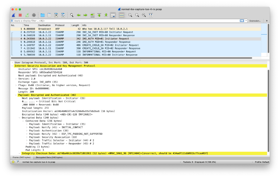
Figure 21: Wireshark can decrypt but not authenticate IKEv2 messages
Now that we have access to the decrypted IKEv2 protocol exchange between firewalls Antwerp and Bruges, we can draw a ladder diagram.
Firewalls Antwerp and Bruges exchange a pair of IKE_SA_INIT and IKE_AUTH messages to establish the IKE security association:
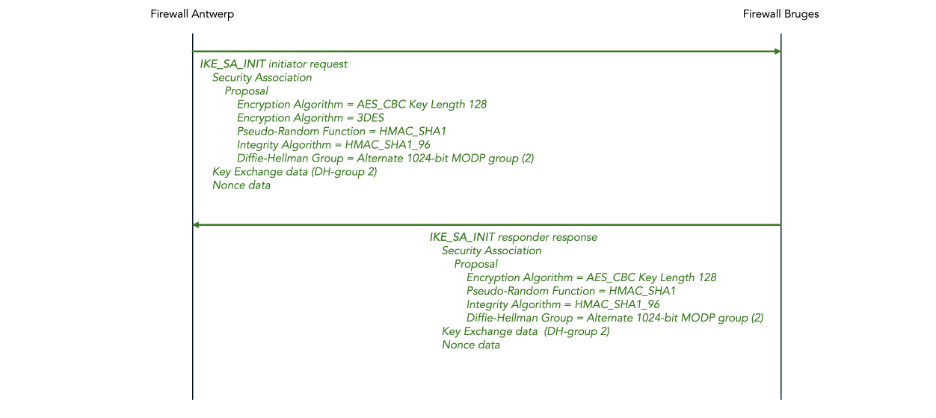
Figure 22: IKEv2 IKE_SA_INIT message exchange (DH keys)
This is followed by an IKE_AUTH exchange:

Figure 23: IKEv2 IKE_AUTH message exchange (DH keys)
Once the IKE security association has been established, firewalls Antwerp and Bruges exchange a CREATE_CHILD_SA message pair to establish the IPsec child security association:
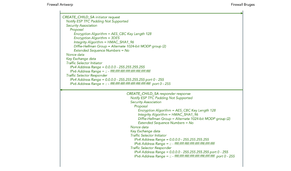
Figure 24: IKEv2 CREATE_CHILD_SA message exchange (DH keys)
5.6 Reconfigure the IPsec tunnel to use PQC key exchange instead of Diffie-Hellman key exchange
We will now re-configure the Palo Alto firewalls to use PQC-produced instead of Diff-Hellman-produced encryption keys for the IPsec tunnel.
Make sure that you have PAN-OS 11.2 or later installed on the Palo Alto firewalls.
Enable the Post-Quantum Key Exchange Mechanism (PQ KEM) for the IKE gateways This requires fragmentation to be enabled as well. We block vulnerable ciphers (i.e. we don’t allow fallback to Diffie-Hellman if PQC is not available) but you may decide differently.
set network ike gateway IKE-GATEWAY protocol ikev2 ikev2-fragment enable yes
set network ike gateway IKE-GATEWAY protocol ikev2 pq-kem enable yes
set network ike gateway IKE-GATEWAY protocol ikev2 pq-kem block-vulnerable-cipher yes
set network ike gateway IKE-GATEWAY protocol ikev2 ikev2-fragment enable yes
set network ike gateway IKE-GATEWAY protocol ikev2 pq-kem enable yes
set network ike gateway IKE-GATEWAY protocol ikev2 pq-kem block-vulnerable-cipher yes
Create a new IKE Crypto Profile:
- We select AES-128-CBC encryption (you may choose AES-256-CBC instead if you wish to double the key length from 128 to 256 because of Grover’s algorithm).
- We select SHA-1 as the hash algorithm.
- We select group20 as the Diffie-Hellman group.
- We enable the Additional Key Exchange (AKE) mechanism.
- We select Kyber-512 as Additional Key Exchange (AKE) number 1. Kyber is the predecessor for Module Lattice Key Encapsulation Method (ML-KEM) standardized in NIST FIPS 203 (it appears that ML-KEM is not yet available in the version of PAN-OS 11.2 that I was using).
set network ike crypto-profiles ike-crypto-profiles PQC-IKE-CRYPTO-PROFILE encryption aes-128-cbc
set network ike crypto-profiles ike-crypto-profiles PQC-IKE-CRYPTO-PROFILE hash sha1
set network ike crypto-profiles ike-crypto-profiles PQC-IKE-CRYPTO-PROFILE dh-group group20
set network ike crypto-profiles ike-crypto-profiles PQC-IKE-CRYPTO-PROFILE ake enabled yes
set network ike crypto-profiles ike-crypto-profiles PQC-IKE-CRYPTO-PROFILE ake ake-1 kyber-512
set network ike crypto-profiles ike-crypto-profiles PQC-IKE-CRYPTO-PROFILE lifetime hours 8
set network ike crypto-profiles ike-crypto-profiles PQC-IKE-CRYPTO-PROFILE encryption aes-128-cbc
set network ike crypto-profiles ike-crypto-profiles PQC-IKE-CRYPTO-PROFILE hash sha1
set network ike crypto-profiles ike-crypto-profiles PQC-IKE-CRYPTO-PROFILE dh-group kyber-512
set network ike crypto-profiles ike-crypto-profiles PQC-IKE-CRYPTO-PROFILE ake enabled yes
set network ike crypto-profiles ike-crypto-profiles PQC-IKE-CRYPTO-PROFILE ake ake-1 bike-L3
set network ike crypto-profiles ike-crypto-profiles PQC-IKE-CRYPTO-PROFILE lifetime hours 8
Create a new IPsec Crypto Profile similar to the IKA Crypto Profile:
set network ike crypto-profiles ipsec-crypto-profiles PQC-IPSEC-CRYPTO-PROFILE esp encryption aes-128-cbc
set network ike crypto-profiles ipsec-crypto-profiles PQC-IPSEC-CRYPTO-PROFILE esp authentication sha1
set network ike crypto-profiles ipsec-crypto-profiles PQC-IPSEC-CRYPTO-PROFILE dh-group group20
set network ike crypto-profiles ipsec-crypto-profiles PQC-IPSEC-CRYPTO-PROFILE ake ake-1 kyber-512
set network ike crypto-profiles ipsec-crypto-profiles PQC-IPSEC-CRYPTO-PROFILE lifetime hours 1
Reconfigure the IKE gateway to use the newly created IKE crypto profile PQC-IKE-CRYPTO-PROFILE:
set network ike gateway IKE-GATEWAY protocol ikev2 ike-crypto-profile PQC-IKE-CRYPTO-PROFILE
set network ike gateway IKE-GATEWAY protocol ikev2 ike-crypto-profile PQC-IKE-CRYPTO-PROFILE
Reconfigure the IPsec tunnel to use the newly created IPsec crypto profile IPSEC-IKE-CRYPTO-PROFILE:
set network tunnel ipsec IPSEC-TUNNEL auto-key ipsec-crypto-profile PQC-IPSEC-CRYPTO-PROFILE
set network tunnel ipsec IPSEC-TUNNEL auto-key ipsec-crypto-profile PQC-IPSEC-CRYPTO-PROFILE
This results in the following configuration hierarchy (we only shows the changed parts, and we only show the configuration for firewall Antwerp):
network {
  ike {
    crypto-profiles {
      ike-crypto-profiles {
        PQC-IKE-CRYPTO-PROFILE {
          encryption aes-256-cbc;
          hash sha512;
          lifetime {
            hours 8;
          }
          ake {
            enabled yes;
            ake-1 kyber-512;
          }
          dh-group group20;
        }
      }
      ipsec-crypto-profiles {
        PQC-IPSEC-CRYPTO-PROFILE {
          esp {
            encryption aes-256-gcm;
            authentication sha512;
          }
          dh-group group20;
          ake {
            ake-1 kyber-512;
          }
          lifetime {
            hours 1;
          }
        }
      }
    }
    gateway {
      IKE-GATEWAY {
        protocol {
          version ikev2;
          ikev2 {
            ike-crypto-profile PQC-IKE-CRYPTO-PROFILE;
            ikev2-fragment {
              enable yes;
            }
            pq-kem {
              enable yes;
              block-vulnerable-cipher yes;
            }
            pq-ppk {
              enabled no;
              negotiation-mode preferred;
            }
            dpd {
              enable no;
            }
          }
          ikev1 {
            dpd {
              enable no;
            }
          }
        }
        authentication {
          pre-shared-key {
            key -AQ==WeZTNpxFiwkjboqhOTmFh5cA3VI=F154Qe6FztgnnzZga/VUbQ==;
          }
        }
        peer-address {
          ip 10.0.2.22;
        }
        local-address {
          interface ethernet1/1;
        }
        protocol-common {
          nat-traversal {
            enable no;
          }
          fragmentation {
            enable no;
          }
        }
      }
    }
  }
  tunnel {
    ipsec {
      IPSEC-TUNNEL {
        auto-key {
          ike-gateway {
            IKE-GATEWAY;
          }
          ipsec-crypto-profile PQC-IPSEC-CRYPTO-PROFILE;
        }
        tunnel-interface tunnel.1;
      }
    }
  }
}
Here are screenshot of what the new configuration looks like in the Web interface:

Figure 25: The PQC-enabled IKE Crypto Profile (General Tab)
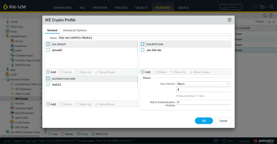
Figure 26: The PQC-enabled IKE Crypto Profile (Advanced Options Tab)
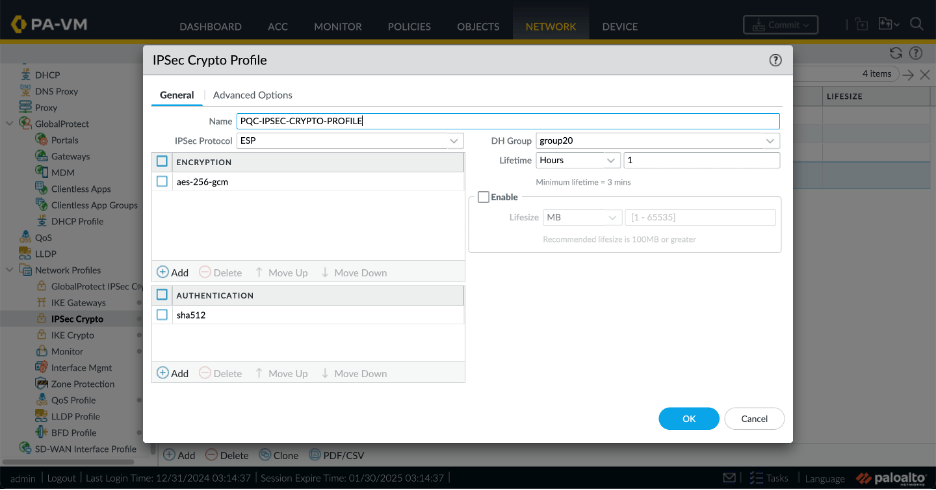
Figure 27: The PQC-enabled IPsec Crypto Profile (General Tab)
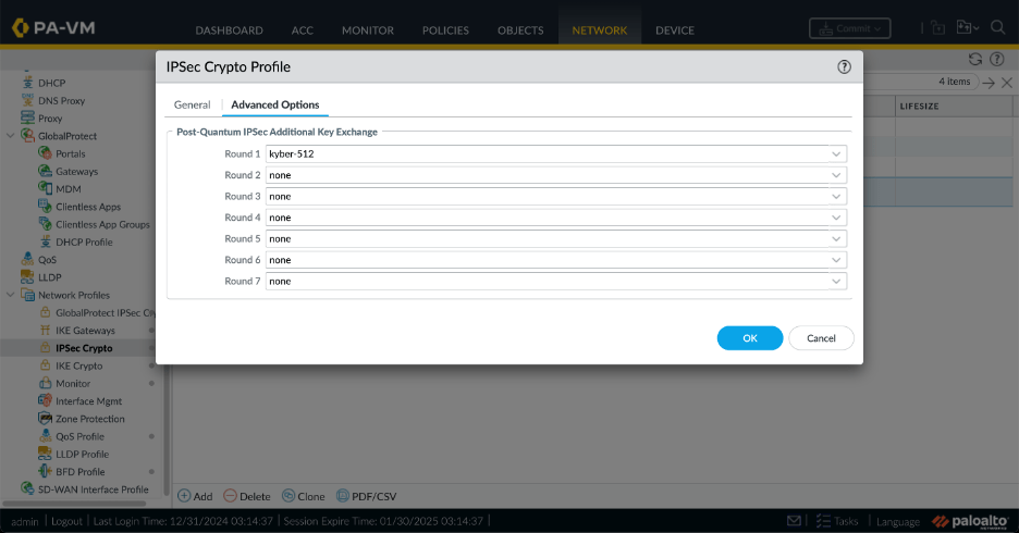
Figure 28: The PQC-enabled IPsec Crypto Profile (Advanced Options Tab)
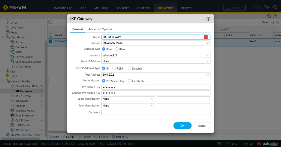
Figure 29: The PQC-enabled IKE Gateway (General Tab)

Figure 30: The PQC-enabled IKE Gateway (Advanced Option Tab)
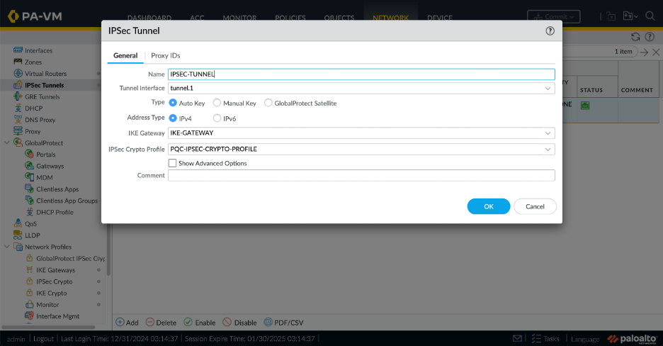
Figure 31: The PQC-enabled IPsec Tunnel
5.7 Verify that the IPsec tunnel (using PQC keys) comes up
Bring the tunnel up:
admin@antwerp> test vpn ike-sa

Start time: Dec.31 04:25:07
Initiate 1 IPSec SA
admin@bruges> test vpn ike-sa

Start time: Dec.31 04:25:26
Initiate 1 IPSec SA.
Verify that the PQC-enabled IKE security association is up:
admin@antwerp> show vpn ike-sa

There is no IKEv1 phase-1 SA found.

There is no IKEv1 phase-2 SA found.


IKEv2 SAs
Gateway ID      Peer-Address           Gateway Name                                                    Role SN       Algorithm                                                        Established     Expiration      Xt Child  ST
----------      ------------           ------------                                                    ---- --       ---------                                                        -----------     ----------      -- -----  --
1               10.0.2.22              IKE-GATEWAY                                                     Init 15       PSK/DH20/A256/SHA512/KYBER-512                                   Dec.31 04:45:34 Dec.31 12:45:34 0  1      Established

IKEv2 IPSec Child SAs
Gateway Name                                                    TnID     Tunnel                                                          ID       Parent   Role SPI(in)  SPI(out) MsgID    ST
------------                                                    ----     ------                                                          --       ------   ---- -------  -------- -----    --
IKE-GATEWAY                                                     1        IPSEC-TUNNEL                                                    14       15       Init 9F35C353 C21DF545 00000002 Mature

Show IKEv2 SA: Total 1 gateways found. 1 ike sa found.
Verify that the PQC-enabled IPsec security association is up:
admin@antwerp> show vpn ipsec-sa

GwID/client IP  TnID   Peer-Address           Tunnel(Gateway)                                                                                                                  Algorithm                                                        SPI(in)  SPI(out) life(Sec/KB)             remain-time(Sec)
--------------  ----   ------------           ---------------                                                                                                                  ---------                                                        -------  -------- ------------             ----------------
1               1      10.0.2.22              IPSEC-TUNNEL(IKE-GATEWAY)                                                                                                        ESP/G256/   /DH20/KYBER-512                                      9F35C353 C21DF545 3600/Unlimited           2437

Show IPSec SA: Total 1 tunnels found. 1 ipsec sa found.
Verify that the PQC-enabled IPsec tunnel is up:
admin@antwerp> show vpn tunnel

TnID   Name                                                            Gateway                                                         Local Proxy IP       Ptl:Port   Remote Proxy IP      Ptl:Port   Proposals
----   ----                                                            -------                                                         --------------       --------   ---------------      --------   ---------
1      IPSEC-TUNNEL                                                    IKE-GATEWAY                                                     0.0.0.0/0            0:0        0.0.0.0/0            0:0        ESP tunl [DH20][AES256-GCM16][SHA512][KYBER-512] 3600s-sec 0s-
                                                                                                                                                                                                       kb

Show IPSec tunnel config: Total 1 tunnels found.
We can see that the PQC-enabled IPsec tunnel is up using the Web interface on the Network > IPsec Tunnels screen:

Figure 32: PQC-enabled tunnel is up in Web interface
Verify that we can ping from the loopback of firewall Antwerp to the loopback of firewall Bruges:
admin@antwerp> ping source 11.11.11.11 host 22.22.22.22
PING 22.22.22.22 (22.22.22.22) from 11.11.11.11 : 56(84) bytes of data.
64 bytes from 22.22.22.22: icmp_seq=1 ttl=64 time=70.9 ms
64 bytes from 22.22.22.22: icmp_seq=2 ttl=64 time=3.01 ms
64 bytes from 22.22.22.22: icmp_seq=3 ttl=64 time=2.95 ms
64 bytes from 22.22.22.22: icmp_seq=4 ttl=64 time=3.24 ms
^C
--- 22.22.22.22 ping statistics ---
4 packets transmitted, 4 received, 0% packet loss, time 8ms
rtt min/avg/max/mdev = 2.945/20.014/70.857/29.354 ms--- 22.22.22.22 ping statistics ---
6 packets transmitted, 6 received, 0% packet loss, time 11ms
rtt min/avg/max/mdev = 1.998/3.825/7.604/1.789 ms
5.8 Capture and decode the IKEv2 exchange (using PQC keys)
Capture and decode a packet trace of the IKEv2 message exchange when the IPsec tunnel is established, using the method described in section 5.5.
As mentioned in section 5.5, extracting the IKEv2 encryption keys SK_ei and SK_er was already a painful process for DH-generated keys. For PQC-generated keys, it becomes nigh-impossible. One reason for this, is that in the PQC case there are multiple different intermediate values for SK_ei and SK_er as described in section 3.3.1 of RFC9242. These multiple values have to be individually extracted from the log files without any clear information in the log file about which intermediate step a key belongs to. Another reason this is very painful is that the current version of Wireshark 4.4.2 only allows a single key value pair SK_ei and SK_er to be configured for a given SA. Thus, we have to manually update the Wireshark configuration to decode different IKE_INTERMEDIATE and IKE_AUTH messages. I will not attempt to describe the steps and instead just give you the ladder diagrams below.
You need a recent version of Wireshark to decode the recent extensions to IPsec for PQC. Wireshark version 4.4.2 works for me.
The IKE_SA_INIT message for PQC-generated keys looks very similar to the IKE_SA_INIT message for DH-generated keys. There are several interesting things to note:
- The SA proposal in the IKE_SA_INIT still contains a Diffie-Hellman group. We changed it from group 2 to group 20, but it is still there. The PQC key has not replaced the DH key. Instead, the PQC key is produced in addition to DH key, and the two keys are combined into the final key, as described in RFC 9370. The combined key is as strong as the strongest contributing key. This way, if the PQC algorithm (Kyber in this case) turns out to be unsafe, we have at least still the safety of Diffie-Hellman (and vice versa).
- The SA proposal in the IKE_SA_INIT does not propose any PQC key generation algorithm. This will come later in the IKE_INTERMEDIATE message.
- There is a IKEv2 Fragmentation Supported notification. This is required because PQC key generation algorithms tend to use large key exchange data fields which may not fit in a a single IKE_INTERMEDIATE message.
- RFC9370 renames transform type “Diffie-Hellman Group Num” to “Key Exchange Method”. Wireshark still uses the old name, which will turn out to be confusing in the IKE_INTERMEDIATE message below.
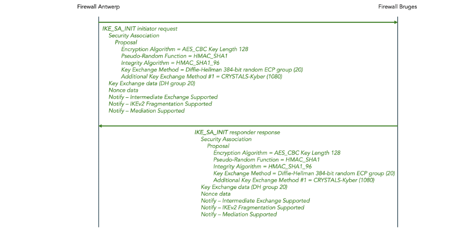
Figure 33: IKEv2 IKE_SA_INIT message exchange (PQC keys)
Next, the initiator and the responder each send an IKE_INTERMEDIATE message.
- In each case, this message is fragmented into two fragments. Wireshark reports the contents of the re-assembled message in the final fragment.
- Wireshark reports Diffie-Hellman group 1080, but this is really key exchange method 1080 (see the note about the confusing terminology above).
- Key exchange method 1080, which is reserved for private use in the IANA registry. Evidently, Palo Alto uses this for Kyber. The official code points for NIST-standardized ML-KEM allocated by IANA are 35, 36, and 37. But evidentially the tested version of PAN-OS does not yet support ML-KEM.
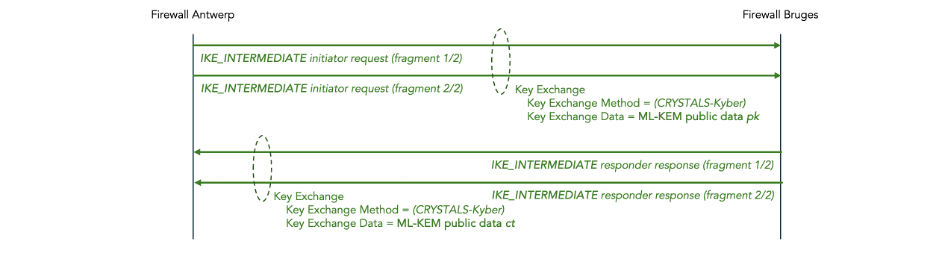
Figure 34: IKEv2 IKE_INTERMEDIATE message exchange (PQC keys)
Finally, the firewalls do an IKE_AUTH exchange. These messages are the same as in the DH-generated key scenario, except that the initiator does not propose 3DES as an encryption protocol, but that’s only because we did not include 3DES in the profile (it has nothing to do with PQC).
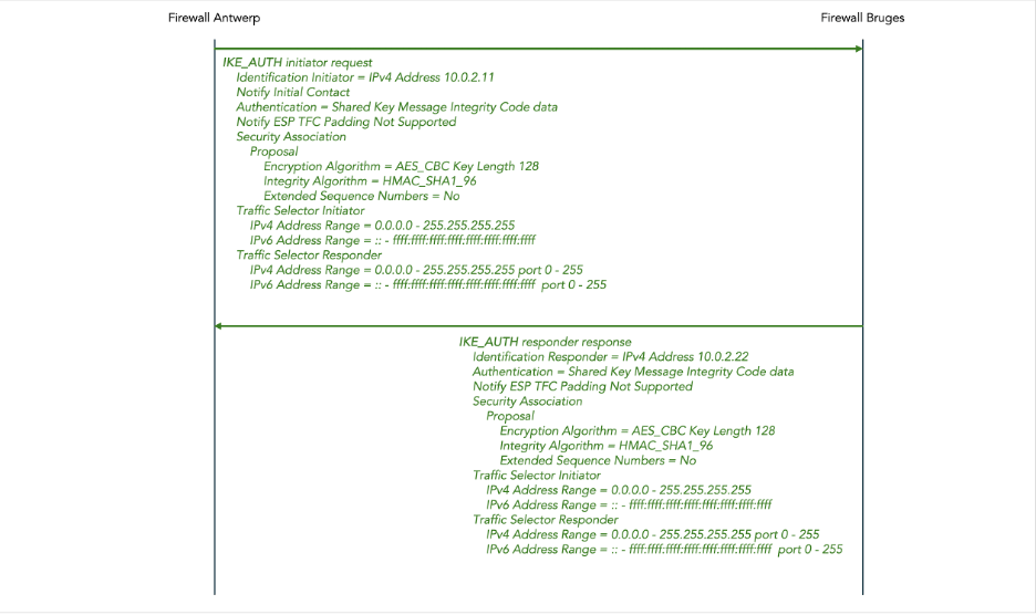
Figure 35: IKEv2 IKE_AUTH message exchange (PQC keys)
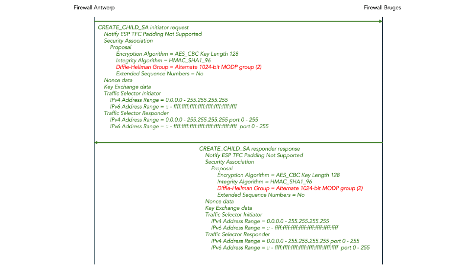
Figure 36: IKEv2 CREATE_CHILD_SA message exchange (PQC keys)
Appendix: Create AWS resources using the AWS console
In this appendix we provide step-by-step instruction for manually configuring two Palo Alto VM-series EC2 instances and the necessary VPC network resources to connect them using the AWS console.
These resources will cost money, even if you still qualify for the free tier in AWS. Amazon will charge you for the AWS resources such as instances and elastic IP addresses. And we use the pay-as-you-go (PAYG) flavor of the Palo Alto VM-Series firewall which incurs an addition hourly fee of around US$ 1.85 per hour after the initial 15-day free trial period expires. The free trial only covers one instance and we will need two. Do not forget to delete the AWS resources after you are done with the tutorial to avoid a nasty surprise on your AWS bill.
In the instructions below, attribute values in bold are different from the Amazon default value. If an attribute value is not explicitly given, accept the default value.
Log in to AWS console https://console.aws.amazon.com/
Create a VPC:
- Go to Services > Networking & Content Delivery > VPC
- Click Create VPC
- Resources to create = VPC only
- Name tag = palo-alto-vpc
- IPv4 CIDR block = manual input
- IPv4 CIDR = 10.0.0.0/16
- IPv6 CIDR block = No IPv6 CIDR block
- Tenancy = default
- Click Create VPC
Create the Internet gateway and attach it to VPC palo-alto-vpc:
- Go to Services > Networking & Content Delivery > VPC > Internet gateways
- Click Create internet gateway
- Name tag = palo-alto-igw
- Click Create internet gateway
- Click Attach to a VPC
- Available VPCs = Select palo-alto-vpc
- Click Attach internet gateway
Create the management subnet:
- Go to Services > Networking & Content Delivery > VPC > Subnets
- Click Create subnet
- VPC ID = select palo-alto-vpc
- Subnet name = palo-alto-mgmt
- Availability zone = No preference
- IPv4 VPC CIDR block = 10.0.0.0/16
- IPv4 VPC CIDR bock = 10.0.1.0/24
- Click Create subnet
Create the management route table and associate it with subnet palo-alto-mgmt:
- Go to Services > Networking & Content Delivery > VPC > Route tables
- Click Create route table
- Name = palo-alto-mgmt-rt
- VPC = Select palo-alto-vpc
- Click Create route table
- Click Edit routes
- Click Add route
- Destination = 0.0.0.0/0
- Target = Internet Gateway
- Select palo-alto-igw as the target Internet gateway
- Click Save changes
- Click the Subnet associations tab
- Click Edit subnet associations
- Select subnet palo-alto-mgmt
- Click Save associations
Create the untrusted subnet:
- Go to Services > Networking & Content Delivery > VPC > Subnets
- Click Create subnet
- VPC ID = select palo-alto-vpc
- Subnet name = palo-alto-untrust
- Availability zone = No preference
- IPv4 VPC CIDR block = 10.0.0.0/16
- IPv4 VPC CIDR bock = 10.0.2.0/24
- Click Create subnet
Create a key pair to SSH into both Palo Alto firewalls:
- Go to Services > Compute > EC2 > Key Pairs
- Click Create key pair
- Name = palo-alto-key-pair
- Key pair type = RSA
- Key file format = .pem
- Click Create key pair
- This will automatically download a file palo-alto-key-pair.pem to your computer
- Move the file to your ~/.ssh directory and set the permissions:
| $ mv ~/Downloads/palo-alto-key-pair.pem ~/.ssh $ chmod 400 ~/.ssh/palo-alto-key-pair.pem |
- Set an environment variable for the location of the SSH key (you may want to add this to your shell profile):
| $ export PALO_ALTO_SSH_KEY=”$HOME/.ssh/palo-alto-key-pair.pem” |
Create the Palo Alto Antwerp instance:
- Note: this round-about way of launching the instance is necessary to be able to choose the version of PAN-OS.
- Go to Cloud Financial Market > AWS Marketplace > Manage Subscriptions
- Click VM-Series Next-Gen Virtual Firewall w/ Advanced Security Subs (PAYG)
- Click Read more on AWS Marketplace
- Click View purchase options
- The screen should say “You’re subscribed to this software”
- Click Continue to Configuration
- Fulfillment option = 64-bit (x86) Amazon Machine Image (AMI)
- Software version = 11.2 latest version, which is 11.2.3-h3 (Nov 19, 2024) when this was written.
- Region = region of your choice
- Click Continue to Launch
- Choose Action = Launch through EC2
- Click Launch
- Name = palo-alto-antwerp
- Application and OS Images (Amazon Machine Image) = pre-filled to PA-VM-AWS-11.2….
- Instance type = c5n.xlarge
- Key pair (login) = Select palo-alto-key-pair
- Click Edit in Network Settings
- VPC = palo-alto-vpc
- Subnet => palo-alto-mgmt
- Auto-assign public IP =>Disable
- Select Create security group
- Security group name = palo-alto-antwerp-mgmt-sg
- Description = Palo Alto Antwerp mgmt security group
- Inbound Security Group Rule 1: Type = SSH, Source type = Anywhere
- Inbound Security Group Rule 2: Type = HTTPS, Source type = Anywhere
- Accept defaults for storage (60 GiB gp2)
- Click Launch instance
Name the management interface for the Palo Alto Antwerp instance:
- Go to Services > Compute > EC2 > Network Interfaces
- Look for the newly created interface without a name
- Click pencil icon in the name column for the newly created interface
- Enter name palo-alto-antwerp-mgmt-if
Create an allow everything security group:
- Go to Services > Compute > EC2 > Security Groups
- Click Create security group
- Security group name = allow-everything-sg
- Description = Allow everything security group
- VPC = Select palo-alto-vpc
- Inbound rules: click Add Rule
- Type = All traffic
- Source = Anywhere-IPv4
- Click Create security group
Create the untrust interface for Palo Alto Antwerp and attach it:
- Go to Services > Compute > EC2 > Network Interfaces
- Click Create network interface
- Description = Palo Alto Antwerp untrust interface
- Subnet = Select palo-alto-untrust
- Private IPv4 address = Custom
- IPv4 address = 10.0.2.11
- Elastic Fabric Adapter = Disable (don’t click Enable)
- Security group = Select allow-everything-sg
- Click Create network interface
- Click View network interface
- Select Actions > Attach
- VPC = palo-alto-vpc
- Instance = palo-alto-antwerp
- Click Attach
Create the public IP address for Palo Alto Antwerp and associate it:
- Go to Services > Compute > EC2 > Elastic IPs
- Click Allocate Elastic IP address
- Public IPv4 address pool = Amazon’s pool of IPv4 addresses
- Click Allocate
- Click Associate this Elastic IP address
- Resource type = Select Network interface
- Network interface = Select palo-alto-antwerp-mgmt-if
- Private IP address = Select the only address in the list (10.0.1.something)
- Click Associate
- Set an environment variable for the public IP address allocated to Palo Alto Antwerp (you may want to add this to your shell profile):
$ export PALO_ALTO_ANTWERP_IP="allocated-public-ip-address"
Create the Palo Alto Bruges instance:
- Note: once again, this round-about way of launching the instance is necessary to be able to choose the version of PAN-OS.
- Go to Cloud Financial Market > AWS Marketplace > Manage Subscriptions
- Click VM-Series Next-Gen Virtual Firewall w/ Advanced Security Subs (PAYG)
- Click Read more on AWS Marketplace
- Click View purchase options
- The screen should say “You’re subscribed to this software”
- Click Continue to Configuration
- Fulfillment option = 64-bit (x86) Amazon Machine Image (AMI)
- Software version = 11.2 latest version, which is 11.2.3-h3 (Nov 19, 2024) when this was written.
- Region = region of your choice
- Click Continue to Launch
- Choose Action = Launch through EC2
- Click Launch
- Name = palo-alto-bruges
- Application and OS Images (Amazon Machine Image) = pre-filled to PA-VM-AWS-11.2….
- Instance type = c5n.xlarge
- Key pair (login) = Select palo-alto-key-pair
- Click Edit in Network Settings
- VPC = palo-alto-vpc
- Subnet => palo-alto-mgmt
- Auto-assign public IP =>Disable
- Select Create security group
- Security group name = palo-alto-bruges-mgmt-sg
- Description = Palo Alto Bruges mgmt security group
- Inbound Security Group Rule 1: Type = SSH, Source type = Anywhere
- Inbound Security Group Rule 2: Type = HTTPS, Source type = Anywhere
- Accept defaults for storage (60 GiB gp2)
- Click Launch instance
Name the management interface for the Palo Alto Bruges instance:
- Go to Services > Compute > EC2 > Network Interfaces
- Look for the newly created interface without a name
- Click pencil icon in the name column for the newly created interface
- Enter name palo-alto-bruges-mgmt-if
Create the untrust interface for Palo Alto Bruges and attach it:
- Go to Services > Compute > EC2 > Network Interfaces
- Click Create network interface
- Description = Palo Alto Bruges untrust interface
- Subnet = Select palo-alto-untrust
- Private IPv4 address = Custom
- IPv4 address = 10.0.2.22
- Elastic Fabric Adapter = Disable (don’t click Enable)
- Security group = Select allow-everything-sg
- Click Create network interface
- Click View network interface
- Select Actions > Attach
- VPC = palo-alto-vpc
- Instance = palo-alto-bruges
- Click Attach
Create the public IP address for Palo Alto Bruges and associate it:
- Go to Services > Compute > EC2 > Elastic IPs
- Click Allocate Elastic IP address
- Public IPv4 address pool = Amazon’s pool of IPv4 addresses
- Click Allocate
- Click Associate this Elastic IP address
- Resource type = Select Network interface
- Network interface = Select palo-alto-bruges-mgmt-if
- Private IP address = Select the only address in the list (10.0.2.something)
- Click Associate
- Set an environment variable for the public IP address allocated to firewall Bruges (you may want to add this to your shell profile):
$ export PALO_ALTO_BRUGES_IP="allocated-public-ip-address"
SSH into Palo Alto Antwerp:
- It takes a few minutes for the instance to completely boot.
- If the SSH connection times out, wait a few minutes.
- If the SSH connection asks for a password, wait a few minutes.
$ ssh -i $PALO_ALTO_SSH_KEY admin@$PALO_ALTO_ANTWERP_IP
The authenticity of host '99.80.21.247 (99.80.21.247)' can't be established.
RSA key fingerprint is SHA256:80kVJ0yJX/1e+pcu1bCY4DdpoQY0hd8XTaUDii+3iZw.
This key is not known by any other names
Are you sure you want to continue connecting (yes/no/[fingerprint])? yes
Warning: Permanently added '99.80.21.247' (RSA) to the list of known hosts.
Welcome admin.
admin@PA-VM>
Set the admin password for Palo Alto Antwerp:
- Choose a password
- Enter the following commands in the CLI of Palo Alto Antwerp to set the password:
admin@PA-VM> configure
Entering configuration mode
[edit]
admin@PA-VM# set mgt-config users admin password
Enter password   : <password>
Confirm password : <password>

[edit]
admin@PA-VM# commit

Commit job 3 is in progress. Use Ctrl+C to return to command prompt
..........55%.98%............100%
Configuration committed successfully
Local configuration size: 11 KB
Predefined configuration size: 14 MB
Merged configuration size(local, panorama pushed, predefined): 17 MB

[edit]
Connect to the Web Interface of Palo Alto Antwerp:
- Open a web browser to the IP address of Palo Alto Antwerp:
$ open https://$PALO_ALTO_ANTWERP_IP
- Assuming you use the Chrome browser, you will get an error “Your connection is not private”
- Click Advanced
- Click proceed to <ip-address> (unsafe)
The Palo Alto login page appears:

- Username = admin
- Password = <password>
- The Palo Alto dashboard page appears:
SSH into Palo Alto Bruges:
- It takes a few minutes for the instance to completely boot.
- If the SSH connection times out, wait a few minutes.
- If the SSH connection asks for a password, wait a few minutes.
$ ssh -i $PALO_ALTO_SSH_KEY admin@$PALO_ALTO_BRUGES_IP
The authenticity of host '176.34.116.102 (176.34.116.102)' can't be established.
RSA key fingerprint is SHA256:9F+Skxzv5fVvdtAOyKUWS3pMf2yq/miDGRsFNwGTb/U.
This key is not known by any other names
Are you sure you want to continue connecting (yes/no/[fingerprint])? yes
Warning: Permanently added '176.34.116.102' (RSA) to the list of known hosts.
Welcome admin.
admin@PA-VM>
Set the admin password for Palo Alto Bruges:
- Choose a password
- Enter the following commands in the CLI of Palo Alto Bruges to set the password:
admin@PA-VM> configure
Entering configuration mode
[edit]
admin@PA-VM# set mgt-config users admin password
Enter password   : <password>
Confirm password : <password>

[edit]
admin@PA-VM# commit

Commit job 3 is in progress. Use Ctrl+C to return to command prompt
..........55%.98%............100%
Configuration committed successfully
Local configuration size: 11 KB
Predefined configuration size: 14 MB
Merged configuration size(local, panorama pushed, predefined): 17 MB

[edit]
Connect to the Web Interface of Palo Alto Bruges:
- Open a web browser to the IP address of Palo Alto Bruges:
$ open https://$PALO_ALTO_BRUGES_IP
- Assuming you use the Chrome browser, you will get an error “Your connection is not private”
- Click Advanced
- Click proceed to <ip-address> (unsafe)
- The Palo Alto login page appears.
- Username = admin
- Password = <password>
- The Palo Alto dashboard page appears.
References
FIPS 197: Advanced Encryption Standard (AES)
FIPS 186-5: Digital Signature Standard (DSS)
FIPS 203: Module-Lattice-Based Key-Encapsulation Mechanism Standard
FIPS 204: Module-Lattice-Based Digital Signature Standard
FIPS 205: Stateless Hash-Based Digital Signature Standard
NIST Special Publication 800-77 Revision 1: Guide to IPsec VPNs
NIST IR 8105: Report on Post-Quantum Cryptography
NIST IR 8547 (Initial Public Draft): Transition to Post-Quantum Cryptography Standards
RFC4301: Security Architecture for the Internet Protocol
RFC4302: IP Authentication Header (AH)
RFC4303: IP Encapsulating Security Payload (ESP)
RFC5996: Internet Key Exchange Protocol Version 2 (IKEv2)
RFC6071: IP Security (IPsec) and Internet Key Exchange (IKE) Document Roadmap
RFC7383: Internet Key Exchange Protocol Version 2 (IKEv2) Message Fragmentation
RFC9242: Intermediate Exchange in the Internet Key Exchange Protocol Version 2 (IKEv2)
RFC 9370: Multiple Key Exchanges in the Internet Key Exchange Protocol Version 2 (IKEv2)
draft-brunner-ikev2-mediation: IKEv2 Mediation Extension
draft-ietf-pquip-pqt-hybrid-terminology: Terminology for Post-Quantum Traditional Hybrid Schemes
draft-ietf-pquip-pqc-engineers: Post-Quantum Cryptography for Engineers
draft-kampanakis-ml-kem-ikev2: Post-quantum Hybrid Key Exchange with ML-KEM in the Internet Key Exchange Protocol Version 2 (IKEv2)
draft-reddy-ipsecme-ikev2-pqc-auth: Signature Authentication in the Internet Key Exchange Version 2 (IKEv2) using PQC
draft-reddy-uta-pqc-app: Post-Quantum Cryptography Recommendations for Internet Applications
National Security Memorandum 10: National Security Memorandum on Promoting United States Leadership in Quantum Computing While Mitigating Risks to Vulnerable Cryptographic Systems
Palo Alto Tech Docs: Learn More About Post-Quantum Security
Palo Alto Tech Docs: Configure Quantum Resistant IKEv2 VPNs.
